
Rotating magnetic field device

A technology of rotating magnetic field and rotating shaft, applied in the direction of magnets, electromagnets, magnetic objects, etc., can solve problems such as complex processes, and achieve the effect of convenient magnetic field strength and convenient adjustment

Inactive Publication Date: 2016-06-08
CHINA JILIANG UNIV
View PDF5 Cites 5 Cited by
  • Summary
  • Abstract
  • Description
  • Claims
  • Application Information

AI Technical Summary

Problems solved by technology

Preparation is the focus of research on gradient functional materials. The preparation process of gradient structure materials requires strict control of parameters such as concentration, flow rate, temperature and pressure, so the process is relatively complicated.

Method used


Image

  • Rotating magnetic field device
  • Rotating magnetic field device
  • Rotating magnetic field device

Examples


Embodiment Construction

[0015] The principles and features of the present invention are described below in conjunction with the accompanying drawings, and the examples given are only used to explain the present invention, and are not intended to limit the scope of the present invention.

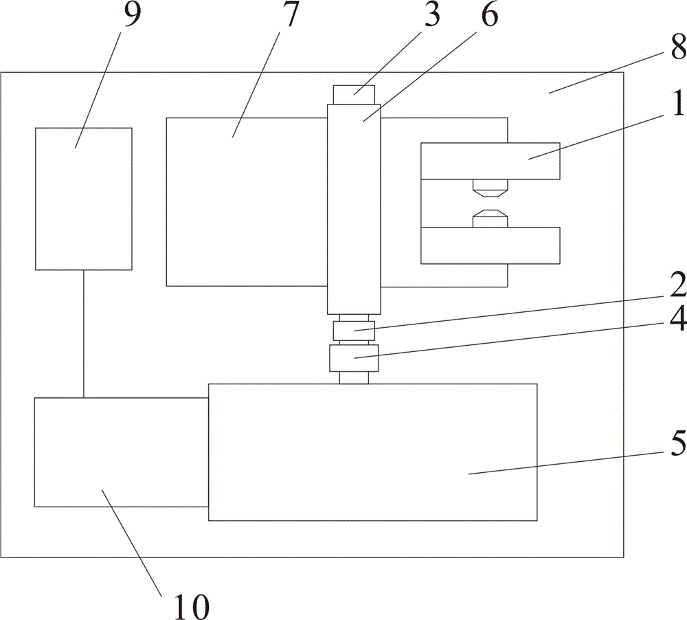
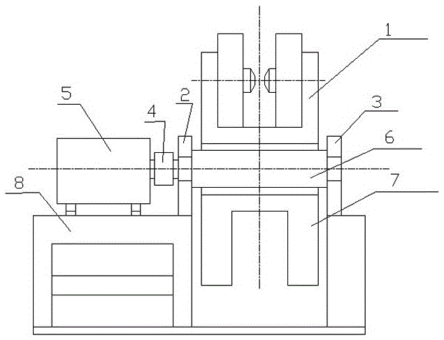
[0016] A rotating magnetic field device, comprising: an electromagnet 1, a bearing seat 2, a bearing seat 3, a counter wheel 4, a reducer 5, a rotating shaft 6, a counterweight iron 7, a bracket 8, a power control cabinet 9, and a motor 10. The electromagnet 1 is in the shape of a capital C and is composed of two sets of electromagnetic coils and an electric iron magnetic circuit. After electrification, a DC magnetic field is provided in the gap; the bearing seat 2 and the bearing seat 3 support the electromagnet 1 symmetrically; the electromagnet 1 passes through the shaft 6. The opposite wheel 4 is connected to the reducer 5; the reducer 5 is connected to the motor 10, and the rotation speed of the motor 10 is redu...


PUM


Abstract

A rotating magnetic field device comprises an electromagnet, bearing pedestals, a coupling wheel, a speed reducer, a rotating shaft, a balance weight, a support, a power source control cabinet and a motor. The electromagnet is in a capital C shape, is composed of two sets of electromagnetic coils and electrical iron magnetic conductive loops and provides a direct-current magnetic field at intervals after being powered on. The two bearing pedestals symmetrically support the electromagnet. The electromagnet is connected with the speed reducer through the rotating shaft and the coupling wheel; the speed reducer is connected with the motor, and power is supplied to rotation of the electromagnet after the rotating speed of the motor is reduced; the balance weight and the electromagnet are symmetrically distributed on the two sides of the rotating shaft, the gravitational torque of the balance weight and the gravitational torque of the electromagnet are equal when the balance weight and the electromagnet rotate, and unbalance caused to the system when the electromagnet rotates can be eliminated; the power source control cabinet is connected with the motor and provides energy for the system, and operation parameters can be set conveniently; the support is located on the lowest position of the whole device and used for supporting all the other structural components. The magnetic field intensity can be adjusted conveniently by adjusting currents, rotation movement perpendicular to the magnetic field direction can be achieved, and the rotation speed is adjustable.

Description

technical field [0001] The invention relates to a magnetic field device, in particular to a rotating magnetic field device. Background technique [0002] Gradient functional materials are different from homogeneous materials and composite materials. It selects two (or more) materials with different properties, and continuously changes the composition and structure of the two (or more) materials to make the interface disappear. The performance of the material changes slowly with the composition and structure of the material, forming a gradient functional material. The concept of gradient materials was first proposed by Japanese scholars in 1987, and scientific research institutions in various countries have carried out such research projects one after another. People have studied the composite theoretical design of thermal stress relaxation FGM, material synthesis technology and structure control methods, and material property evaluation. A lot of important progress and resu...

Claims


Application Information

Patent Timeline
IPC IPC(8): H01F7/20G05F7/00C22F3/00
CPCC22F3/00G05F7/00H01F7/202
Inventor 彭晓领李静杨艳婷徐靖才王攀峰金红晓王新庆葛洪良
Owner CHINA JILIANG UNIV
Learn More