
A rotary stud conveying device

A conveying device and rotary technology, applied in arc welding equipment, manufacturing tools, welding equipment, etc., can solve the problems of stud jamming, increase work cost, instability, etc., and achieve the effect of avoiding jamming and improving work efficiency.

Active Publication Date: 2017-09-29
江门健维自动化设备有限公司
View PDF6 Cites 0 Cited by
  • Summary
  • Abstract
  • Description
  • Claims
  • Application Information

AI Technical Summary

Problems solved by technology

Since the workers are not allowed to put their hands into the welding torch when putting the studs into the welding torch, only tools such as pliers are allowed to clamp the studs into the welding torch, so the position of the studs put into the welding torch often shifts , so that when the stud is driven out of the welding torch, there will be a jamming problem, which will affect the life of the welding torch; or when the stud is driven out of the welding torch for welding, the welding position will be shifted or unstable due to the position of the stud, which needs to be solved. Re-welding, affecting welding efficiency
In addition, manually putting the studs into the welding torch one by one, the work efficiency is also relatively low, which increases the work cost

Method used


Image

  • A rotary stud conveying device
  • A rotary stud conveying device

Examples


Embodiment Construction

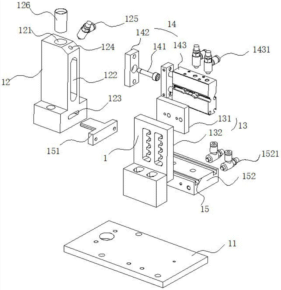
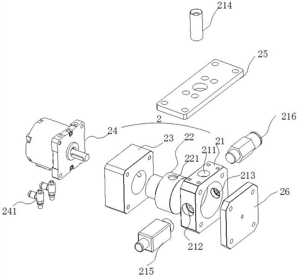
[0014] The rotary stud conveying device provided by the present invention includes a clamping limiting device 1 and a rotary propulsion device 2 located below the clamping limiting device 1 and connected to its output port.

[0015] see figure 1 , which is an exploded view of the clamping and limiting device of the present invention. The clamping and limiting device 1 includes a base 11 , a stud conveying block 12 , a position adjusting block 13 , a clamping device 14 and a limiting device 15 . The stud conveying block 12 is fixed on the base 11 by screws. The stud delivery block 12 is provided with a passage (not shown) for conveying studs; A clamping device socket 122 and a limiting device socket 123 are provided at the side end. The position adjusting block 13 is fixed on the base 11 by screws. The clamping device 14 is fixed on the position adjusting block 13 by screws, and the clamping device 14 is inserted into the channel periodically through the clamping device soc...


PUM


Abstract

The invention discloses a rotary stud conveying device. The rotary stud conveying device comprises a clamping and limiting device and a rotary propelling device connected to an output port of the clamping and limiting device, wherein the rotary propelling device comprises a stud receiving block, a rotary rotor and a rotary rotor driving mechanism; a stud inlet connected to the output port of the stud conveying block is formed in the upper end of the stud receiving block; a stud outlet and an air blowing port which are opposite to each other are formed in two side ends of the stud receiving block respectively; the rotary rotor sleeves in the stud receiving block; a stud receiving opening corresponding to the stud inlet is formed in the upper end of the rotary rotor; the rotary rotor driving mechanism is fixedly connected to the rotary rotor. Through the rotary stud conveying device, the studs conveyed by the clamping and limiting device are received by the rotary rotor; after rotating at 90 degrees, the studs are blown out of the rotary rotor under the pushing of the external compressed air and are stably fixed in a welding gun; the studs can be accurately and fully automatically conveyed to the welding gun; the working efficiency is improved.

Description

technical field [0001] The invention relates to the field of stud conveying, in particular to a rotary stud conveying device. Background technique [0002] As a commonly used auxiliary connecting part, studs are widely used in boilers, automobiles, shipbuilding and other fields. During welding, it is usually necessary to put the stud into the welding torch, use the welding torch to make the welding surface of the stud contact with the surface of the welding workpiece, and generate an arc between the two, and then form a molten pool on the welding workpiece; when the contact surface is fully melted, then Quickly apply a certain pressure to the stud through the welding torch, so that it can be inserted into the molten pool of the welding workpiece at a controlled speed; when the welding arc is extinguished, the metal on the contact surface between the two solidifies, so that the stud and the welding workpiece are closely connected. At present, workers usually take out the stu...

Claims


Application Information

Patent Timeline
Patent Type & Authority Patents(China)
IPC IPC(8): B23K9/20B23K9/32
CPCB23K9/206B23K9/327
Inventor 卢育兵
Owner 江门健维自动化设备有限公司
Learn More