Realization method of transmitting and receiving multiplexing antenna structure applied to vehicle radar

A technology for multiplexing antennas and implementation methods, which is applied to the structural connection of antenna grounding switches, antennas, antenna arrays and other directions, which can solve the problem that the installation and measurement requirements of vehicle-mounted radar cannot be well met, and the antenna beam angle and radar antenna size cannot be ensured at the same time. , The installation area of ​​the vehicle radar is limited, etc., to solve the contradiction between the antenna beam angle and the size of the radar, the structure is ingenious, and the size of the radar is small.

Active Publication Date: 2019-03-29
CHENGDU ANZHIJIE TECH CO LTD
View PDF5 Cites 0 Cited by
  • Summary
  • Abstract
  • Description
  • Claims
  • Application Information

AI Technical Summary

Problems solved by technology

However, due to the limited installation area of ​​the vehicle radar, this requires the radar size to be as small as possible
At the same time, the vehicle-mounted radar system determines that the radar antenna must meet the requirements of simultaneous transmission and reception. Therefore, under the condition of limited aperture, the transmitting and receiving antennas each occupy a part of the aperture, resulting in the effective aperture of the transmitting and receiving antenna becoming smaller.
[0009] It can be seen that the existing vehicle-mounted radar antennas cannot meet the installation and measurement requirements of vehicle-mounted radars well because they cannot ensure a small antenna beam angle and radar antenna size at the same time.

Method used


Image

  • Realization method of transmitting and receiving multiplexing antenna structure applied to vehicle radar
  • Realization method of transmitting and receiving multiplexing antenna structure applied to vehicle radar
  • Realization method of transmitting and receiving multiplexing antenna structure applied to vehicle radar

Examples


Embodiment Construction

[0026] The present invention will be further described below with reference to the accompanying drawings and embodiments, and the mode of the present invention includes but not limited to the following embodiments.

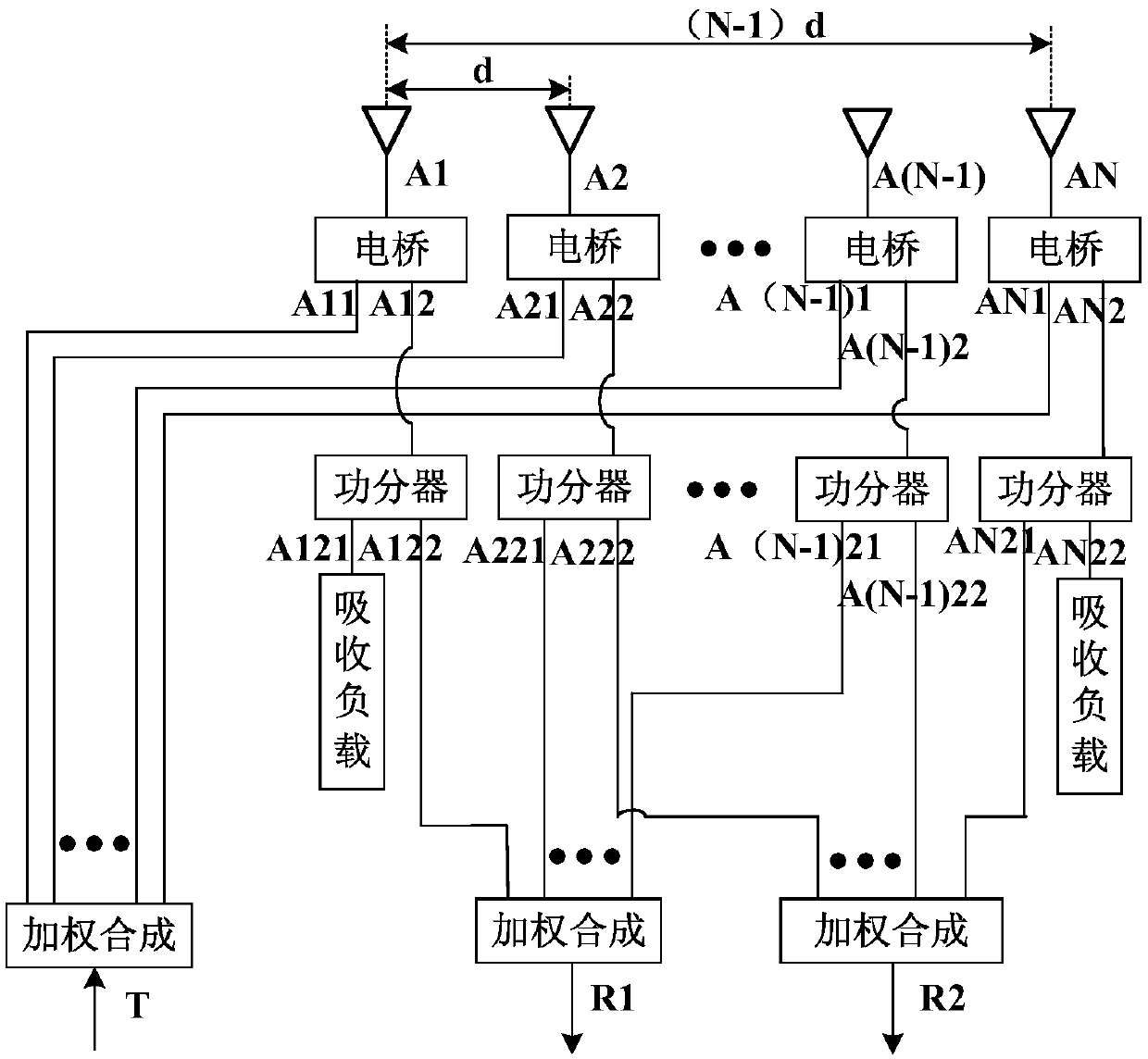
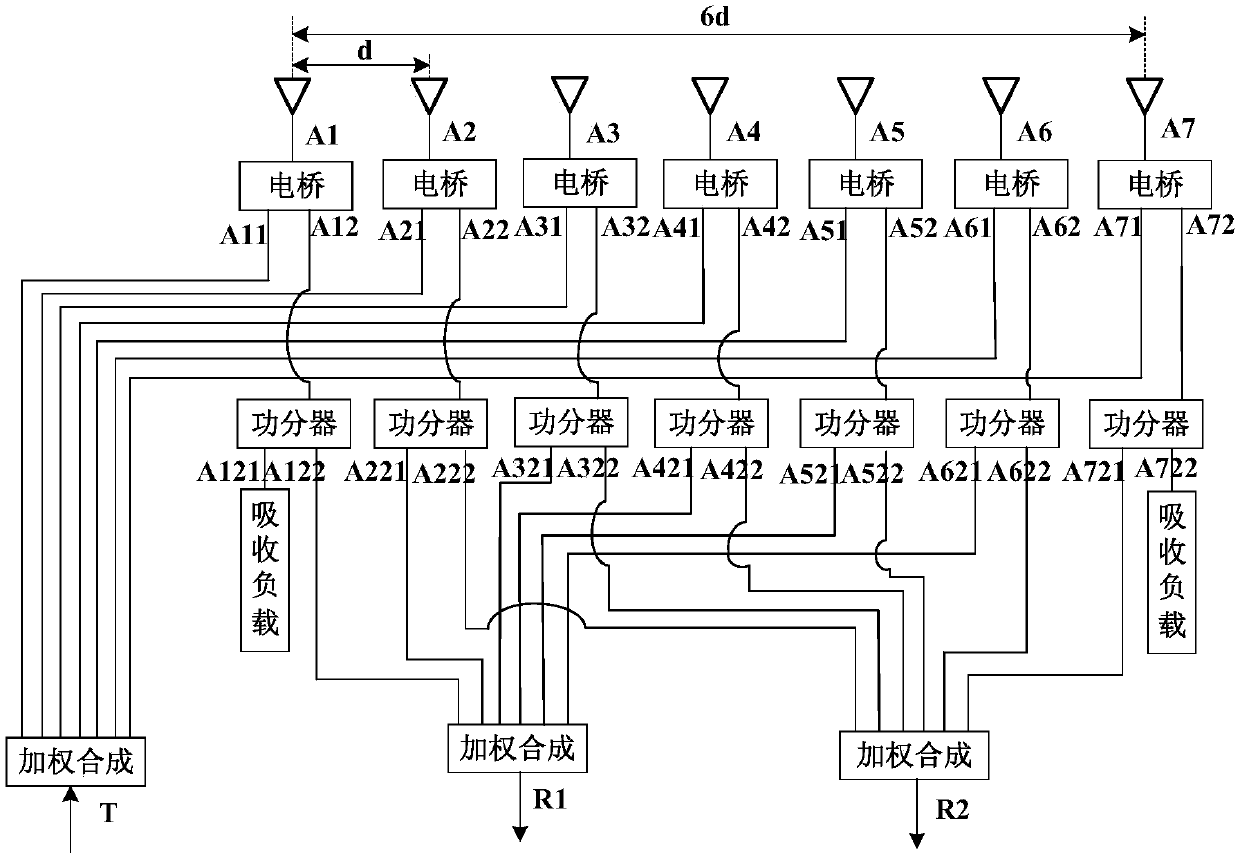
[0027] Such as figure 1 As shown, the present invention provides a vehicle-mounted radar transceiver multiplexing antenna, which includes an antenna array, an electric bridge, a power splitter and a weighted network, wherein:

[0028] The antenna array is composed of N antenna array elements, where N is greater than 1, and the distance between adjacent antenna array elements is d.

[0029] There are M bridges, 1


PUM


Abstract

The invention discloses a receiving-transmitting multiplexing antenna structure applied to a vehicle-mounted radar and an implementation method thereof. In the field of vehicle-mounted radars, in order to improve the measurement accuracy of the radar, the beam angle of an antenna needs to be as small as possible, so as to concentrate energy for achieving longer detection distance and reducing noise jamming, and meanwhile the size of the radar needs to be as small as possible, thus being convenient to mount. The invention provides an antenna array element multiplexing structure and an antenna array element multiplexing method, for dividing the antenna array element power into multiple parts, and then the power of every array element is weighed to form a transmitting antenna and two receiving antennas for transmitting and receiving signals. According to the receiving-transmitting multiplexing antenna structure applied to the vehicle-mounted radar, the receiving-transmitting isolation problem is solved by electrical bridges, the receiving beam width is reduced through multiplexing of power dividers, and thereby the antenna area of the radar is reduced in an array element multiplexing way. The receiving-transmitting multiplexing antenna structure applied to the vehicle-mounted radar is reasonable in design and ingenious in structure, and well meets the requirement on miniaturized antenna of the vehicle-mounted radar, thus being applicable to popularization and application.

Description

technical field [0001] The invention relates to a vehicle-mounted radar antenna, in particular to a method for realizing a transmit-receive multiplexing antenna structure applied to a vehicle-mounted radar. Background technique [0002] Currently the most used vehicle radar antenna, assuming that there are M+2N (M≥1, N≥1) array element antennas in its technology, a column of antennas is an array element, and the array elements are T1, T2...TM, R11, R12...R1N, R21, R22...R2N, in which the array elements T1, T2...TM are weighted according to a certain rule to form a T transmitting antenna, and the distance between the array elements is d, then its azimuth beamwidth is: [0003] [0004] Among them, λ is the wavelength, M is the number of array elements, and d is the distance between array elements. [0005] The array elements R11, R12...R1N are weighted according to a certain law to form an R1 receiving antenna, and the array elements R21, R22...R2N are weighted according ...

Claims


Application Information

Patent Timeline
Patent Type & Authority Patents(China)
IPC IPC(8): H01Q21/00H01Q1/50
CPCH01Q21/0012
Inventor 左丽花张建军
Owner CHENGDU ANZHIJIE TECH CO LTD
Why Eureka
Try Eureka