
Aircraft coating application system and method

An aircraft, coating technology, used in coating, robotics, aircraft maintenance and other directions

Active Publication Date: 2016-02-10
THE BOEING CO
View PDF6 Cites 14 Cited by
  • Summary
  • Abstract
  • Description
  • Claims
  • Application Information

AI Technical Summary

Problems solved by technology

The painting process is also challenged by the large amount of exterior surface area of ​​the aircraft

Method used


Image

  • Aircraft coating application system and method
  • Aircraft coating application system and method
  • Aircraft coating application system and method

Examples


Embodiment Construction

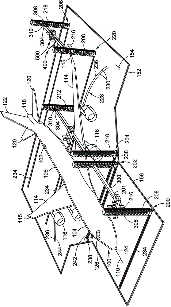
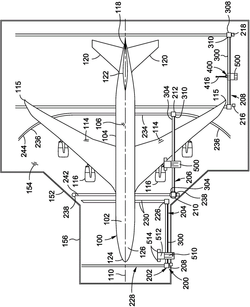
[0099] Referring now to the drawings, where shown are for purposes of illustrating various embodiments of the present disclosure, figure 1 Shown in is a perspective view of one embodiment of a coating application system 200 . Coating application system 200 represents an automated system and method for performing operations related to applying a coating, such as painting exterior surface 102 of aircraft 100 . In this regard, the coating application system 200 and the methods disclosed herein provide a means for accessing areas external to an aircraft in order to perform one or more of a variety of operations mechanically (e.g., automatically or semiautomatically) and / or manually item, the various operations described include, but are not limited to: sanding, cleaning, surface preparation, masking, priming, coating, unmasking, inspection, and Any of a variety of other operations.

[0100] exist Figure 1 to Figure 4 In the example, the coating application system 200 may inclu...


PUM


Abstract

The invention relates to an aircraft coating application system and method. The coating application system may include a pair of towers movable along a respective pair of floor tracks. A crossbeam may extend between the pair of towers. The cross beam may have opposing beam ends. A universal joint may couple each beam end to a tower to allow the crossbeam to rotate about a vertical axis and about a horizontal axis. A robotic device may be mounted to the crossbeam. The robotic device may include an end effector for performing one or more operations on an aircraft exterior surface.

Description

technical field [0001] The present invention relates to aircraft coating application systems and methods. Background technique [0002] Due to the wide range of sizes and unique geometries associated with aircraft, aircraft painting is a challenging and time-consuming process. For example, an airfoil extending outward from the fuselage presents a geometry that can affect the painting process. The height of the vertical stabilizer above the horizontal stabilizer may present challenges in accessing the outer surface of the vertical stabilizer. In this regard, the process of painting an aircraft may require personnel to access the exterior surfaces of the aircraft to perform tasks such as surface sanding, cleaning, and masking prior to applying one or more layers of primer and paint after unmasking and inspecting the exterior surfaces of the aircraft. manual operation. [0003] And the operation of applying the coating to the outer surfaces of the aircraft must be carried ou...

Claims


Application Information

Patent Timeline
Patent Type & Authority Applications(China)
IPC IPC(8): B05C9/00B05C11/00B05D7/14
CPCB64F5/30B64F5/50B64F5/40B64F5/45Y10S901/43B05B13/005B05B3/02B05B12/02B25J11/0075B05B13/0431B25J5/04
Inventor D·R·马蒂斯
Owner THE BOEING CO
Learn More