
A sound chamber structure and mobile terminal

A mobile terminal and sound cavity technology, applied in the field of sound cavity, can solve problems such as poor sealing of sound cavity channels, and achieve the effects of avoiding scraper problems, accurate assembly positioning, and ensuring sealing

Active Publication Date: 2018-06-12
GUANGDONG OPPO MOBILE TELECOMM CORP LTD
View PDF5 Cites 1 Cited by
  • Summary
  • Abstract
  • Description
  • Claims
  • Application Information

AI Technical Summary

Problems solved by technology

[0003] The purpose of the present invention is to provide a sound chamber structure and a mobile terminal to solve the problem of foam sealing in the sound chamber channel in the prior art, or the foam being scraped during the assembly process of the mobile phone, etc. Causes the problem of poor sealing of the sound cavity channel

Method used


Image

  • A sound chamber structure and mobile terminal
  • A sound chamber structure and mobile terminal
  • A sound chamber structure and mobile terminal

Examples


Embodiment 1

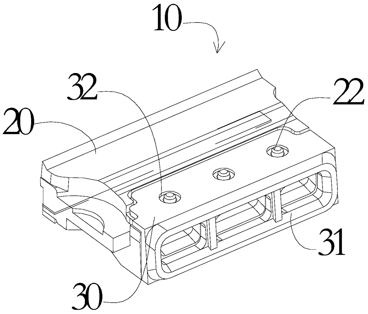
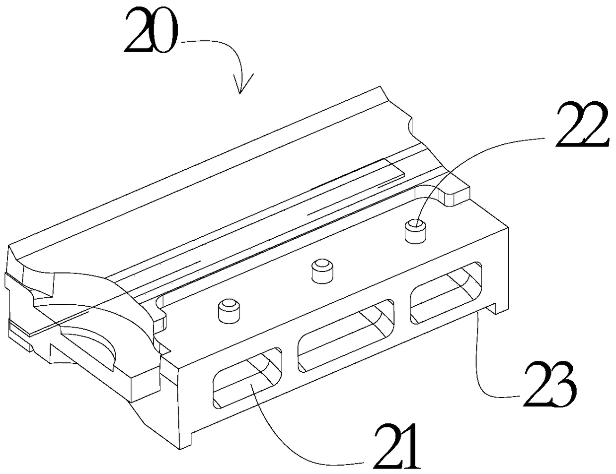
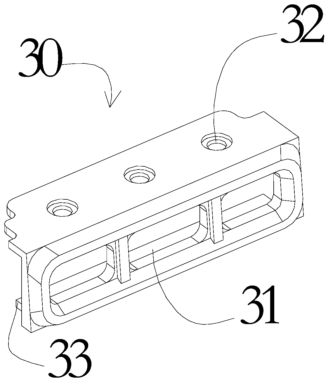
[0024] Please refer to figure 1 , figure 2 with image 3 , figure 1 It is a schematic diagram of the assembly of the sound cavity bracket 20 and the elastic sealing sleeve 30 of the present invention, figure 2 It is a structural schematic diagram of the sound cavity support 20 of the present invention, image 3 It is a structural schematic diagram of the elastic sealing sleeve 30 of the present invention. from Figure 1 to Figure 3 As can be seen:

[0025] A sound cavity structure 10 of the present invention includes a sound cavity support 20 and an elastic sealing sleeve 30 matched therewith, the sound cavity support 20 includes a sound outlet channel 21, and the elastic sealing sleeve 30 includes a sound outlet 31, when When the elastic sealing sleeve 30 is wrapped and fixed outside the sound cavity support 20 , the sound outlet channel 21 of the sound cavity support 20 is matched with the sound outlet 31 of the elastic sealing sleeve 30 .

[0026] In this embodimen...

Embodiment 2

[0032] In this embodiment, a mobile terminal is used as an example of a mobile terminal to describe a mobile terminal in this embodiment in detail.

[0033] A kind of mobile phone of the present invention, it comprises sound cavity structure 10, and described sound cavity structure 10 comprises sound cavity support 20 and the elastic sealing sleeve 30 that cooperates with it, please refer to figure 1 , figure 2 with image 3 , figure 1 It is a schematic diagram of the assembly of the sound cavity bracket 20 and the elastic sealing sleeve 30 of the present invention, figure 2 It is a structural schematic diagram of the sound cavity support 20 of the present invention, image 3 It is a structural schematic diagram of the elastic sealing sleeve 30 of the present invention. from Figure 1 to Figure 3 As can be seen:

[0034] The sound cavity support 20 includes a sound outlet channel 21, and the elastic sealing sleeve 30 includes a sound outlet 31. When the elastic sealing...


PUM


Abstract

The invention discloses a sound cavity structure. The sound cavity structure comprises a sound cavity bracket and an elastic sealing sleeve matched with the sound cavity bracket; the sound cavity bracket comprises a sound output channel; the elastic sealing sleeve comprises a sound outlet; the elastic sealing sleeve is wrapped and fixed outside the sound cavity bracket; and furthermore, the sound output channel of the sound cavity bracket is matched with the sound outlet of the elastic sealing sleeve. According to the invention, the scaling problem easily caused when the mobile terminal is assembled can be avoided; and the sealing property of the sound output channel of the sound cavity bracket can also be ensured.

Description

technical field [0001] The invention relates to the field of sound chambers, in particular to a sound chamber structure and a mobile terminal. Background technique [0002] At present, with the development of society and the advancement of science and technology, electronic products such as mobile phones are becoming more and more important to people's lives, and consumers have higher and higher requirements for electronic products. Taking mobile phones as an example, consumers now have high requirements for the fineness of the appearance of mobile phones. At present, the sound output methods of mobile phone speakers mainly include front sound, rear sound and side sound, among which the sound output methods of front sound and back sound are more common, but these two sound output methods are easy to damage the front touch screen and The integrity of the battery cover on the back affects the fineness of the appearance of the phone. However, the side sound mode avoids the sh...

Claims


Application Information

Patent Timeline
Patent Type & Authority Patents(China)
IPC IPC(8): H04M1/62
Inventor 曾传华
Owner GUANGDONG OPPO MOBILE TELECOMM CORP LTD
Learn More