


Quick Research
Generate reliable direction feasibility study reports for your R&D in just a few steps.

Technical Q&A
Discover and master advanced knowledge NOW. Basics, ideas, possibilities, all at once.

Find Solutions
As an expert in R&D theories, this can generate solutions to your technical problems instantly.

Evaluate Feasibility
Analyze your overall solution with one click, know your potential R&D risks in advance.

Monitor Landscape
Get weekly tech updates, stay abreast of the latest tech innovations and key insights.
Multifunctional lifting device for underwater camera
A lifting device and camera technology, applied in cranes, transportation and packaging, load hoisting components, etc., can solve the problems of unstable shooting pictures and inability to determine the shooting orientation, and achieve the effects of novel conception, convenient operation, and stable camera direction.
- Summary
- Abstract
- Description
- Claims
- Application Information
AI Technical Summary
Problems solved by technology
Method used
Image

Examples
specific Embodiment approach 1
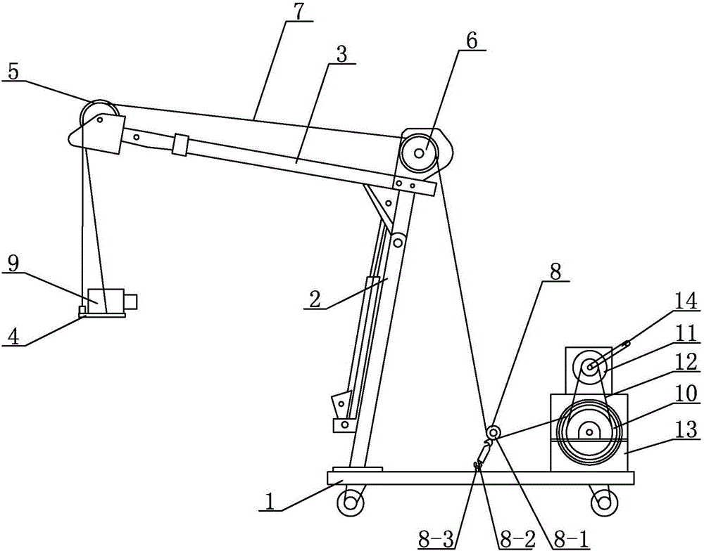
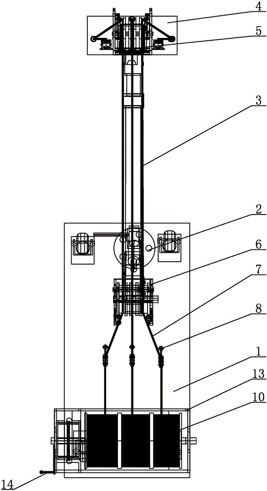
[0008] Specific implementation mode one: combine figure 1 and figure 2 Describe this embodiment mode, a kind of multifunctional lifting device for underwater camera described in this embodiment mode comprises movable trolley 1, crane bracket 2, beam 3, camera base 4, cable winch, three-wire front guide pulley 5, three-wire rear Guide pulley 6, three cables 7 and three cable synchronous position adjustment devices 8, the movable trolley 1 is set horizontally, the crane bracket 2 is installed on the front part of the movable trolley 1, the rear end of the beam 3 is connected with the crane bracket 2, the three-wire front guide pulley 5 is installed on the front end of the beam 3, the three-wire rear guide pulley 6 is installed on the rear end of the beam 3, the cable winch is installed on the rear of the movable trolley 1, and the three cables are synchronized The position adjustment device 8 is installed side by side in the middle of the movable trolley 1, three cables 7 are ...
specific Embodiment approach 2
[0012] Specific implementation mode two: combination figure 1 and figure 2 Describe this embodiment, the cable retracting mechanism of a multifunctional lifting device for an underwater camera described in this embodiment includes a cable winch including a cable reel 10, a transmission wheel 11, a transmission chain 12, a reel support 13 and a crank 14. The cable reel 10 and the transmission wheel 11 are sequentially installed on the reel support 13 from bottom to top, the transmission wheel 11 is connected to the cable reel 10 through the transmission chain 12, and the crank handle 14 is connected to the rotating shaft of the transmission wheel 11. Other components and connections are the same as those in the first embodiment.
specific Embodiment approach 3
[0013] Specific implementation mode three: combination figure 1 and figure 2 Describe this embodiment, each cable synchronous position adjusting device 8 of a kind of underwater camera multifunctional lifting device described in this embodiment includes a pulley 8-1, a cable tensioner 8-2 and a ring screw 8- 3. The pulley 8-1 is connected to the upper end of the cable tensioner 8-2, the lower end of the cable tensioner 8-2 is connected to the ring screw 8-3, and the ring screw 8-3 is fixed on the movable trolley 1 on. Other components and connections are the same as those in the first embodiment.
PUM
 Abstract
Description
Claims
Application Information
 - R&D Engineer
- R&D Manager
- IP Professional
- Industry Leading Data Capabilities
- Powerful AI technology
- Patent DNA Extraction
Browse by: Latest US Patents, China's latest patents, Technical Efficacy Thesaurus, Application Domain, Technology Topic, Popular Technical Reports.
© 2024 PatSnap. All rights reserved.Legal|Privacy policy|Modern Slavery Act Transparency Statement|Sitemap|About US| Contact US: help@patsnap.com