
Ultrasonic diagnostic imaging system with spatial compounding of trapezoidal sector

An ultrasonic diagnosis and imaging system technology, applied in the field of ultrasonic diagnosis and imaging systems of spatial composite images, can solve the problem that the spatial composite effect is not uniform and the like

Active Publication Date: 2015-11-18
KONINKLJIJKE PHILIPS NV
View PDF14 Cites 8 Cited by
  • Summary
  • Abstract
  • Description
  • Claims
  • Application Information

AI Technical Summary

Problems solved by technology

Unfortunately, as discussed below, the spatial compounding effect is not uniform across the image

Method used


Image

  • Ultrasonic diagnostic imaging system with spatial compounding of trapezoidal sector
  • Ultrasonic diagnostic imaging system with spatial compounding of trapezoidal sector
  • Ultrasonic diagnostic imaging system with spatial compounding of trapezoidal sector

Examples


Embodiment Construction

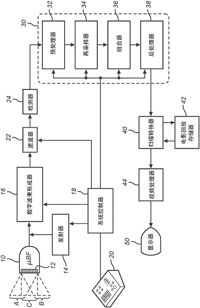
[0011] first reference figure 1 , shows an ultrasonic diagnostic imaging system constructed in accordance with the principles of the present invention. The ultrasound probe 10 includes a planar array transducer 12 that emits beams at different angles over an image field indicated by dashed rectangles and parallelograms outlining the area scanned by steered linear beam scanning. Three sets of scan lines are indicated in the figure, labeled A, B and C, each set being steered at a different angle relative to the face of the array transducer. An array transducer can be a one-dimensional (1D) array of transducer elements or a two-dimensional (2D) matrix array of transducer elements. The emission of the beams is controlled by a transmitter 14 which controls the phasing and timing of actuation of each of the elements of the array transducer so that each beam is emitted along the array and at a predetermined angle from a predetermined origin. When using a 2D array transducer, transm...


PUM


Abstract

An ultrasonic diagnostic imaging system produces spatially compounded trapezoidal sector images by combining component frames acquired from different look directions. A virtual apex scan format is used such that each scanline of a component frame emanates from a different point (El, En) on the face of an array transducer (12) and is steered at a different scanning angle. For different component frames the scanlines are steered at respectively different angles. In the illustrated example, the scanlines of each component frame are incremented by five degrees relative to the corresponding scanlines in a reference component frame. When the component frames are combined for spatial compounding, the maximum number of component frames are combined over virtually the entire image field.

Description

technical field [0001] The present invention relates to ultrasonic diagnostic imaging systems, and more particularly to ultrasonic diagnostic imaging systems that produce spatially compounded images in a trapezoidal sector format. Background technique [0002] Spatial compounding is an imaging technique in which data from multiple vantage points or angles (viewing direction) ) to combine many ultrasound images of a given target into a single composite image. Examples of spatial recombination can be found in US Patents 4,649,327 (Fehr et al); 4,319,489 (Yamaguchi, et al); 4,159,462 (Rocha, et al; 6,210,328 (Robinson, et al); 6,126,598 (Entrekin, et al) and 6,224,552 (Jago et al). Rapid acquisition of a series of spatially overlapping component image frames from substantially independent spatial directions, using array transducers to perform electron beam steering and / or electronic translation of the component frames, to perform real-time spatial compound imaging. By summing,...

Claims


Application Information

Patent Timeline
Patent Type & Authority Applications(China)
IPC IPC(8): G01S15/89G01S7/52
CPCG01S15/8918G01S7/52085G01S15/8925G01S15/8995A61B8/52A61B8/4444A61B8/4494A61B8/488A61B8/5207A61B8/5238G01N29/04A61B8/14A61B8/461
Inventor L·J·奥尔森
Owner KONINKLJIJKE PHILIPS NV
Learn More