
Bottle lifting device for filling machine

A lifting device and filling machine technology, applied in liquid bottling, packaging, bottle filling, etc., can solve problems such as poor sealing of the lifting device, air leakage affecting the life of seals, and bottle mouth leakage, so as to improve filling efficiency The effect of filling accuracy, prolonging service life and simple structure

Active Publication Date: 2017-05-24
GUANGZHOU TECH LONG PACKAGING MACHINERY CO LTD
View PDF9 Cites 1 Cited by
  • Summary
  • Abstract
  • Description
  • Claims
  • Application Information

AI Technical Summary

Problems solved by technology

[0002] The lifting device and the filling valve of the traditional filling machine are two separate and independent parts. The lifting device is below the filling valve and installed on the machine through a fixing piece. Drive the bottle up and down, and the clamping plate lifts the bottle to the sealing place of the filling valve bottle mouth. There is a suspended arm between the two parts. In the place, it will cause poor sealing, air leakage at the bottle mouth during filling, and the guide ring of the lifting device is prone to unilateral force and wear during the lifting process, which will affect the life of the seal, resulting in poor sealing of the lifting device and air leakage

Method used


Image

  • Bottle lifting device for filling machine
  • Bottle lifting device for filling machine
  • Bottle lifting device for filling machine

Examples


Embodiment Construction

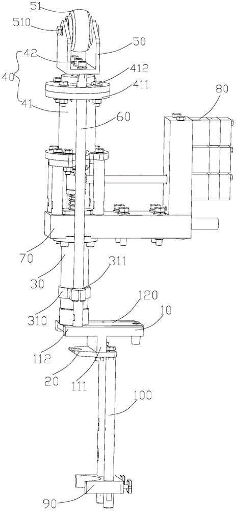
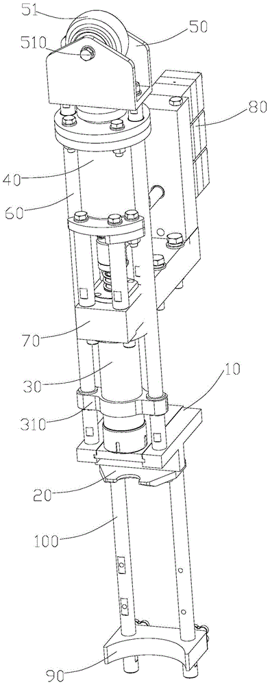
[0023] Such as figure 1 , 2 As shown, a bottle lifting device of a filling machine includes a dummy cup 10, a bottle clamping plate 20, and a cylinder 40 arranged above the filling valve 30. The telescoping part of the cylinder 40 is provided with a roller seat 50. Roller seat 50 is provided with roller 51, and the both sides of described roller seat 50 is provided with guide bar 60 respectively, and the end of described guide bar 60 away from roller seat 50 is connected with described dummy cup 10, and the bottom of described dummy cup 10 The end is connected with the bottle clamping plate 20, the dummy cup 10 is located below the valve port of the filling valve 30, and the axis line of the cylinder 40, the axis line of the filling valve 30 and the longitudinal center line of the roller 51 coincide. The cylinder 40 includes a cylinder seat 41, a piston rod 42 arranged in the cylinder seat 41, and the bottle lifting device of the filling machine also includes a connection se...


PUM


Abstract

The invention relates to a bottle lifting device for a filling machine. The bottle lifting device comprises a false cup, a bottle clamping plate, and a cylinder which is arranged above a filling valve; a roller seat on which a roller is arranged is arranged on a telescopic part of the cylinder; guide rods are respectively arranged at two sides of the roller seat; one end of each guide rod, far away from the roller seat, is connected with the false cup; the bottom end of the false cup is connected with the bottle clamping plate; the false cup is positioned below an opening of the filling valve; axes of the cylinder and the filling valve and a longitudinal center line of the roller are overlapped. According to the bottle lifting device for the filling machine, the roller, the false cup, the bottle clamping plate, the filling valve and the cylinder are connected as a whole structure; the cost is small; when in filling, the cylinder upwards moves under the effect of compacted air, and the bottle clamping plate is driven by the roller seat together with the guide rods to move upwards, so as to prop a bottle opening to the opening of the valve for filling; after the filling, the roller downwards moves, and the bottle clamping plate is driven by the guide rods to downwards move, so as to enable a bottle to be separated from the opening of the valve; the force applied during lifting or lowering is concentrated in the direction of the axis of the filling valve, so that the filling precision can be effectively increased.

Description

technical field [0001] The invention relates to filling equipment technology, in particular to a bottle lifting device of a filling machine. Background technique [0002] The lifting device and the filling valve of the traditional filling machine are two separate and independent parts. The lifting device is below the filling valve and installed on the machine through a fixing piece. Drive the bottle up and down, and the clamping plate lifts the bottle to the sealing place of the filling valve bottle mouth. There is a suspended arm between the two parts. At the place, it will cause poor sealing, air leakage at the bottle mouth during filling, and the guide ring of the lifting device is prone to unilateral force and wear during the lifting process, which will affect the life of the seal and cause air leakage due to poor sealing of the lifting device. Especially for gas-containing filling, a slight vibration will cause the beverage in the bottle to foam and overflow the bottle...

Claims


Application Information

Patent Timeline
Patent Type & Authority Patents(China)
IPC IPC(8): B67C3/24
Inventor 梁业成
Owner GUANGZHOU TECH LONG PACKAGING MACHINERY CO LTD
Learn More