Electronic equipment running method and device
A technology of electronic equipment and operation method, applied in the field of electronics, can solve the problems of main display interface control and weak interactivity in areas that cannot be displayed, and achieve the effects of improving interactivity and applicability and improving operation efficiency.
- Summary
- Abstract
- Description
- Claims
- Application Information
AI Technical Summary
Problems solved by technology
Method used
Image
Examples
Embodiment 1
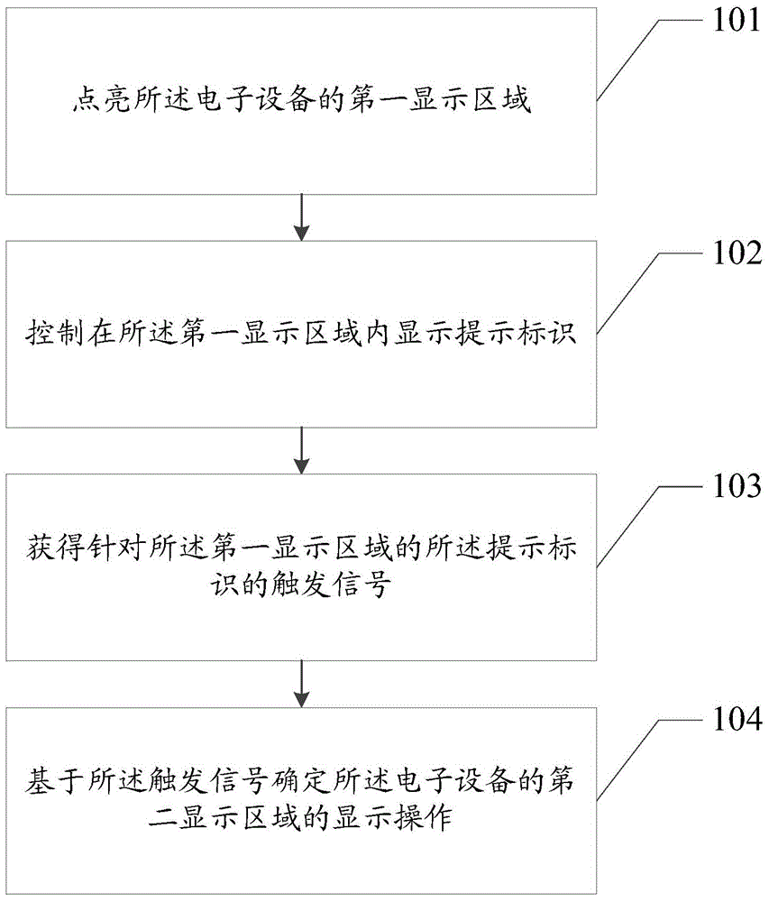
[0073] Please refer to figure 1 , Embodiment 1 of the present application provides a method for operating an electronic device, including:
[0074] Step 101: Light up the first display area of the electronic device.
[0075] The first display area is also the display area on the display interface of the electronic device for displaying prompt information or identification information.
[0076] During the specific implementation of this step, lighting up the first display area may specifically include two situations. One is that the electronic device receives a signal that triggers lighting up of the first display area, for example, when the When the electronic device receives a text message, or when the electronic device receives a prompt message reminding to install an application program update, or the operating state of the electronic device changes, in the above situation, the electronic device needs to be controlled in the first display area To display the correspondi...
Embodiment approach
[0091] Such as Figure 4 As shown, the first implementation mode is: the first display area and the second display area are different display areas in the same display screen, for example, the left and right independent display areas in the same display screen, or use the picture-in-picture Independent display area for drawing mode.
[0092] Such as Figure 5 As shown, the second implementation manner is: the first display area and the second display area are two different display screens that are independent of each other, for example, a mobile phone with two upper and lower independent display screens.
[0093] Such as Figure 6As shown, the third implementation manner is: the first display area and the second display area are display areas located on the same display screen but on different planes of the display screen, for example, the second display area The area may be a display area on the main view plane of a cuboid display screen, and the first display area may be ...
Embodiment 2
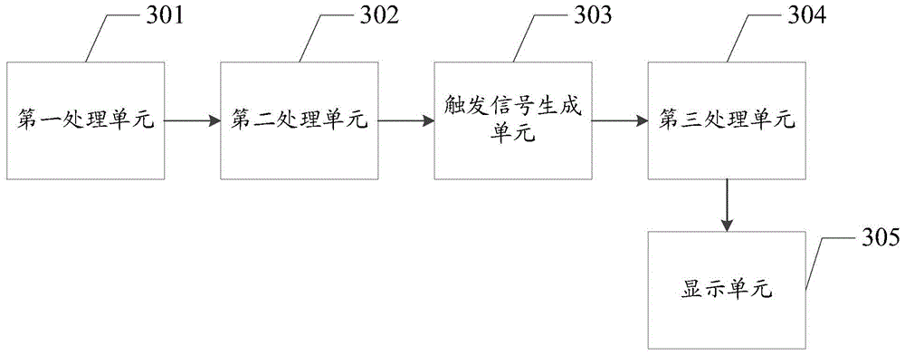
[0135] Please refer to figure 2 , Embodiment 2 of the present application provides an electronic device, including:
[0136] The processor 201 is configured to control the lighting of the first display area of the electronic device, control the display of prompt signs in the first display area, and determine the display operation of the second display area of the electronic device based on the trigger signal ;
[0137] a trigger signal receiver 202, configured to obtain a trigger signal for the prompt mark in the first display area;
[0138] A display 203, including the first display area and the second display area, wherein the first display area is smaller than the second display area, and the first display area and the second display area are not stacked .
[0139] Preferably, the processor is specifically configured to light up the second display area of the electronic device based on the trigger signal, and control the application program corresponding to the tr...
PUM
 Abstract
Description
Claims
Application Information
 - R&D Engineer
- R&D Manager
- IP Professional
- Industry Leading Data Capabilities
- Powerful AI technology
- Patent DNA Extraction
Browse by: Latest US Patents, China's latest patents, Technical Efficacy Thesaurus, Application Domain, Technology Topic, Popular Technical Reports.
© 2024 PatSnap. All rights reserved.Legal|Privacy policy|Modern Slavery Act Transparency Statement|Sitemap|About US| Contact US: help@patsnap.com


