
Displacement sensor for contactless measurement of position by means of several magnetic field sensors arranged in series

A technology of magnetic field sensor and displacement sensor, which is applied in the field of displacement sensor and can solve the problems of low precision and large change of measurement error

Active Publication Date: 2016-04-20
TE CONNECTIVITY GERMANY GMBH
View PDF10 Cites 0 Cited by
  • Summary
  • Abstract
  • Description
  • Claims
  • Application Information

AI Technical Summary

Problems solved by technology

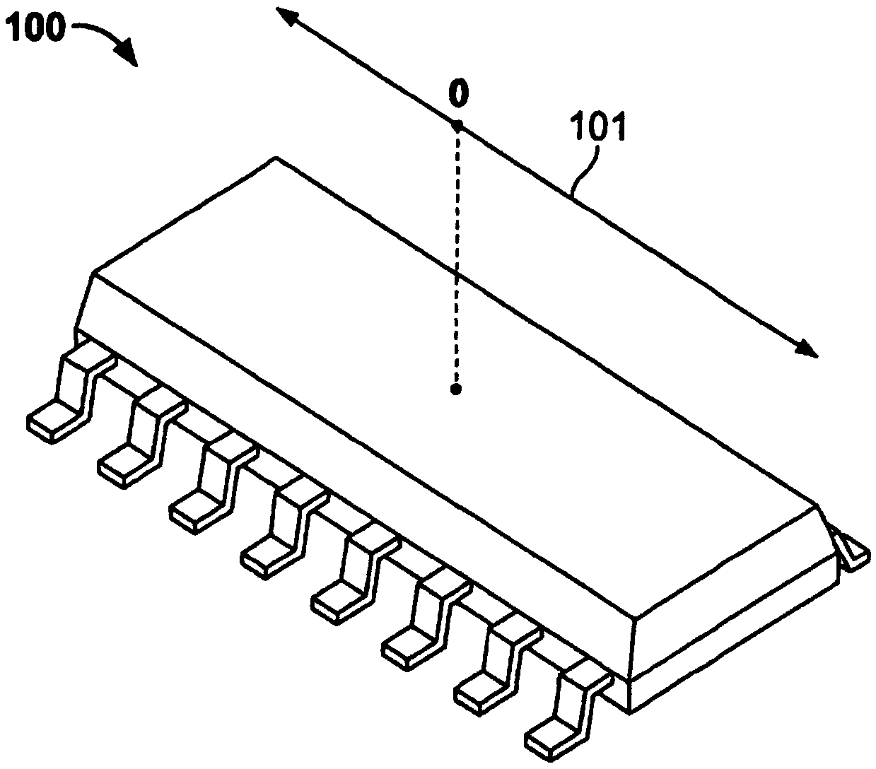
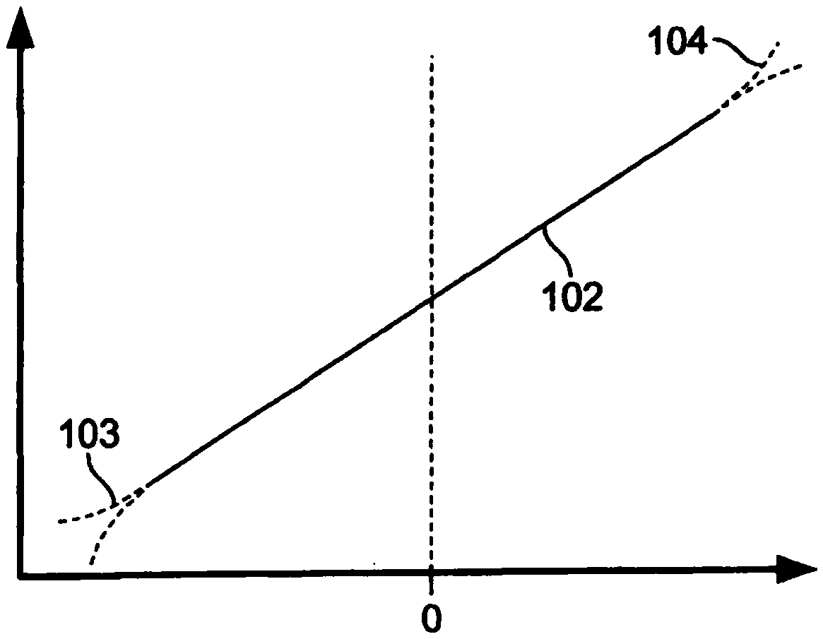
At the two ends 103 and 104 of the displacement measurement range, the variation of the measurement signal and thus the measurement error becomes larger; the linear relationship between the output signal 102 of the sensor and the position of the magnet disappears because the output signal 102 indicates the position of the magnet the precision of the

Method used


Image

  • Displacement sensor for contactless measurement of position by means of several magnetic field sensors arranged in series
  • Displacement sensor for contactless measurement of position by means of several magnetic field sensors arranged in series
  • Displacement sensor for contactless measurement of position by means of several magnetic field sensors arranged in series

Examples


Embodiment Construction

[0041] Hereinafter, the present invention will be described in more detail with reference to the accompanying drawings.

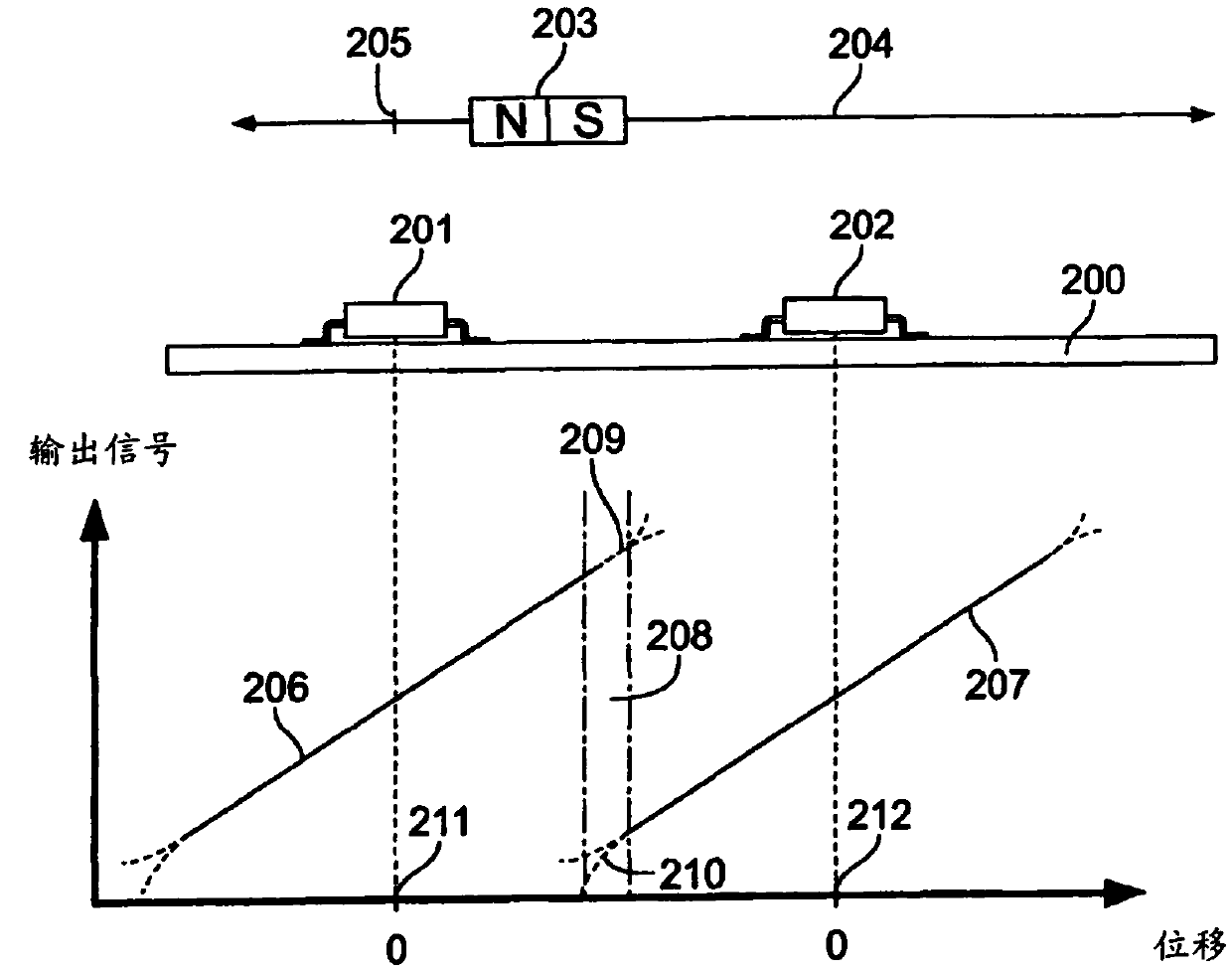
[0042] image 3 A displacement sensor arrangement according to the invention is shown. Two 3D Hall sensors 201 and 202 arranged in series are mounted in a fixed position on the printed circuit board 200 and a magnet 203 , preferably a permanent magnet, is displaceable along a movement axis 204 relative to the two Hall sensors. The N / S axis of the magnet 203 is oriented parallel to the axis of motion 204 . However, this orientation is not strictly necessary. In principle, it is also possible to carry out the invention if the N / S axes of the magnets have a different orientation, eg transverse to said axis of motion.

[0043] Magnets are available from image 3 The reference point 205 shown is shifted. The 3D Hall sensor with the magnet arranged in close proximity detects at least two orthogonal magnetic field components and produces an output signal exte...


PUM


Abstract

The invention relates to a displacement sensor for non-contact measurement of the position of a magnet relative to a reference point. The displacement sensor comprises a magnet displaceable along the axis of motion, a plurality of magnetic field sensors arranged in series and parallel to the axis of motion of the magnet, and a calculation unit forming a position signal indicative of the position of the magnet relative to a reference point. A plurality of magnetic field sensors arranged in series are arranged such that displacement measurement ranges of adjacent magnetic field sensors overlap in overlapping ranges. The calculation unit is configured such that if the magnet position is included in the overlapping range, the calculation unit forms a position signal based on an output signal output by a magnetic field sensor whose displacement measurement range overlaps in the overlapping range; and if the magnet position is not included in the overlapping range, the calculation unit The position signal is formed on the basis of the output signal output by the magnetic field sensor of which the magnet is located in its displacement measuring range. The overlapping range between two displacement measuring ranges of adjacent magnetic field sensors is selected such that the total error of the position signal formed by the calculation unit in this overlapping range is smaller than the maximum permissible error.

Description

technical field [0001] The present invention relates to a displacement sensor for contactless measurement of the position of a magnet based on a plurality of magnetic field sensors arranged in series, in particular to a displacement sensor with a displacement range several times greater than an individual magnetic field sensor. [0002] In the displacement sensor according to the invention, the accuracy of the position signal output by the displacement sensor and indicating the position of the magnet relative to the reference point is intended to be below a maximum permissible error over the entire displacement range. [0003] A typical example of a magnetic field sensor is a Hall sensor. As an example of a magnetic field sensor, the present invention is described with reference to a Hall sensor, but is not limited thereto. Background technique [0004] Hall sensors are used in many cases for controlling machine tools, in automation technology, robotics and in automatic par...

Claims


Application Information

Patent Timeline
Patent Type & Authority Patents(China)
IPC IPC(8): G01D5/14
CPCG01D5/145G01B7/004
Inventor S.斯塔克
Owner TE CONNECTIVITY GERMANY GMBH
Learn More