Optical body, optical body manufacturing method, solar shading member, window member, interior member, and fitting
A technology of optical body and optical layer, applied in the field of optical body, can solve problems such as temperature rise and achieve the effect of suppressing the overall reduction
Active Publication Date: 2015-01-21
DEXERIALS CORP
View PDF2 Cites 3 Cited by
- Summary
- Abstract
- Description
- Claims
- Application Information
AI Technical Summary
Problems solved by technology
[0008] In other words, the above-mentioned directional reflector has a problem that as the directional reflection component decreases, a larger amount of sunlight reaches the ground and causes an increase in temperature near the ground surface
Method used
View moreImage
Smart ImageViewing Examples

Examples
no. 1 approach
[0054] First Embodiment (Example of Optical Body Forming Reflective Layer in Pyramid Pattern)
no. 2 approach
[0055] Second Embodiment (Example of Sunshade Device Using Optical Body)
no. 3 approach
[0056] Third Embodiment (another example of a solar shading device in which an optical body is applied to a roller shade device)
Login to View More PUM
| Property | Measurement | Unit |
|---|---|---|
| wavelength | aaaaa | aaaaa |
| wavelength | aaaaa | aaaaa |
| surface roughness | aaaaa | aaaaa |
Abstract
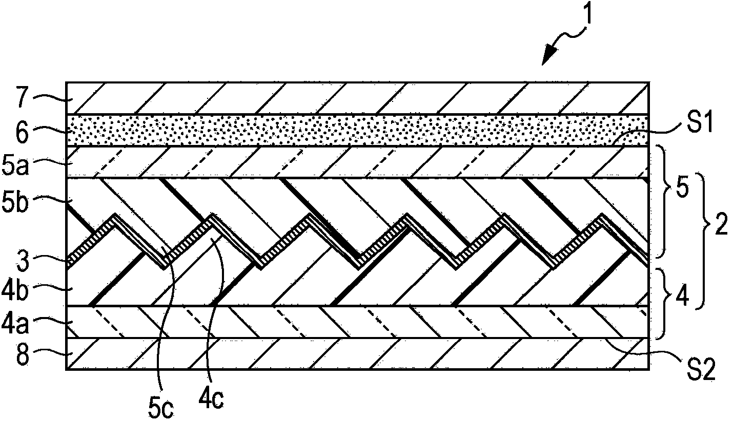
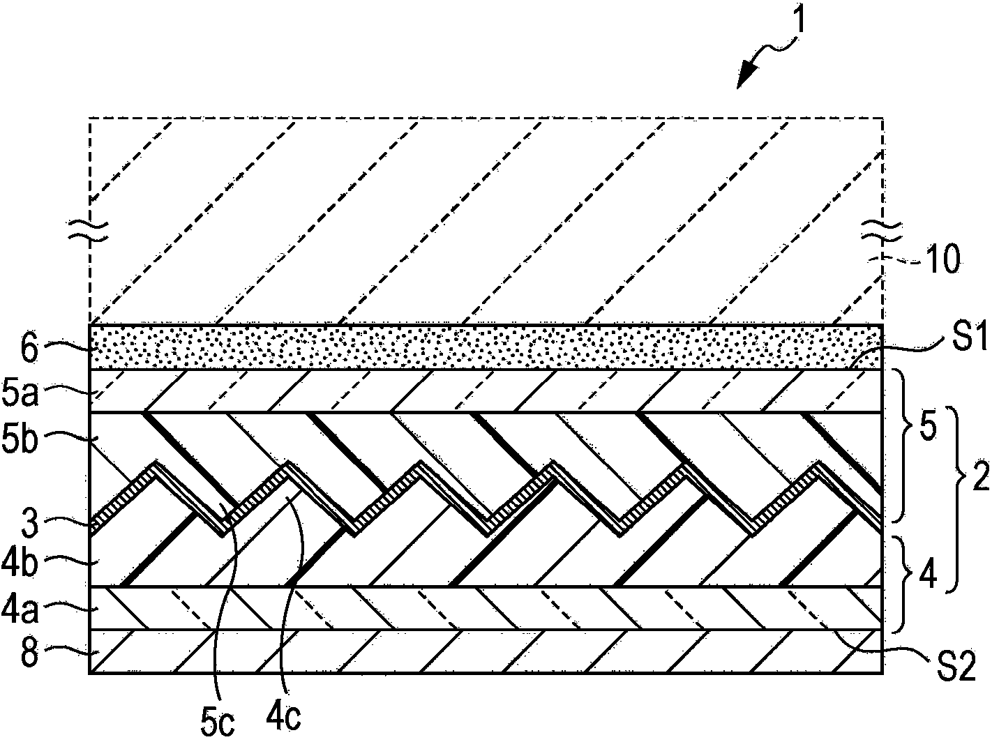
An optical body includes a first optical layer, a second optical layer having an incident surface on which light is incident, and a reflecting layer sandwiched between the first and second optical layers, wherein the first optical layer includes a plurality of convex or concave structures formed on or in a surface thereof on which the reflecting layer is disposed, ridges of the convex structures or ridges between the concave structures adjacent to each other have tip portions projecting toward the incident surface side, the tip portions are deformed from an ideal shape, the second optical layer is transparent and has a refractive index of 1.1 or more and 1.9 or less, and the optical body selectively directionally reflects part of light entering the incident surface, which part is in a specific wavelength band, in direction other than the specular reflection direction.
Description
technical field [0001] The present invention relates to an optical body, a method of manufacturing the optical body, a solar shielding member, a window member, an interior member, and a building member. In particular, the invention relates to optical bodies for directional reflection of incident light. Background technique [0002] Recently, cases of coating a layer that partially absorbs or reflects sunlight on architectural glass for high-rise buildings and houses, automobile window glass, and the like have increased. Such a trend is one of the energy-saving measures aimed at preventing global warming, and is also intended to reduce the load on the cooling device that increases due to sunlight energy that enters the room through the window and raises the room temperature. [0003] The light energy introduced by the sun is mainly provided by light in the visible range with a wavelength of 380nm to 780nm and light in the near infrared range with a wavelength of 780nm to 210...
Claims
Login to View More Application Information
Patent Timeline
 Patent Type & Authority Applications(China)
IPC IPC(8): G02B5/08B32B3/30B32B37/02E06B9/24
CPCE06B9/386E06B9/24B60J1/2041G02B5/124E06B2009/2417G02B5/208G02B5/0808B32B3/30B32B37/02
Inventor 影山正光吉田宽则谷岛胜行长浜勉榎本正
Owner DEXERIALS CORP
Features
- Generate Ideas
- Intellectual Property
- Life Sciences
- Materials
- Tech Scout
- Unparalleled Data Quality
- Higher Quality Content
- 60% Fewer Hallucinations
Learn More Browse by: Latest US Patents, China's latest patents, Technical Efficacy Thesaurus, Application Domain, Technology Topic, Popular Technical Reports.
© 2025 PatSnap. All rights reserved.Legal|Privacy policy|Modern Slavery Act Transparency Statement|Sitemap|About US| Contact US: help@patsnap.com