Multifunctional isolating switch

An isolating switch, multi-functional technology, applied in the direction of electric switches, measuring devices, instruments, etc., can solve the problem of only having the function of making and breaking the current

Inactive Publication Date: 2014-12-17
SCHNEIDER ELECTRIC IND SAS
View PDF6 Cites 2 Cited by
  • Summary
  • Abstract
  • Description
  • Claims
  • Application Information

AI Technical Summary

Problems solved by technology

At present, the common isolating switches on the market are just a device for mechanically connecting and breaking current, and generally only have the functions of current making and breaking.

Method used


Image

  • Multifunctional isolating switch
  • Multifunctional isolating switch
  • Multifunctional isolating switch

Examples


Embodiment Construction

[0027] The invention provides a multifunctional isolating switch with one or more functions among current detection function, monitoring control function, digital display function and communication function. Now refer to the attached figure 1 -5 to introduce in detail the multifunctional isolating switch according to the present invention.

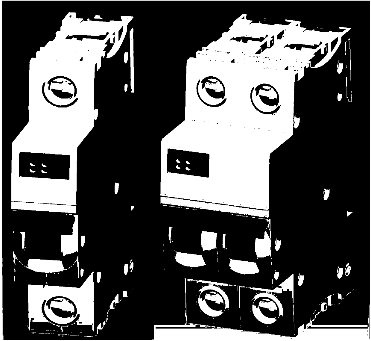
[0028] figure 1 It shows the appearance diagram of the isolating switch according to the present invention. The left is the model appearance of the unipolar product, and the right is the model appearance of the bipolar product 1P+N. The isolating switch according to the invention is substantially identical in appearance to conventional isolating switches, except that it has a digital display (88A) regarding the current.

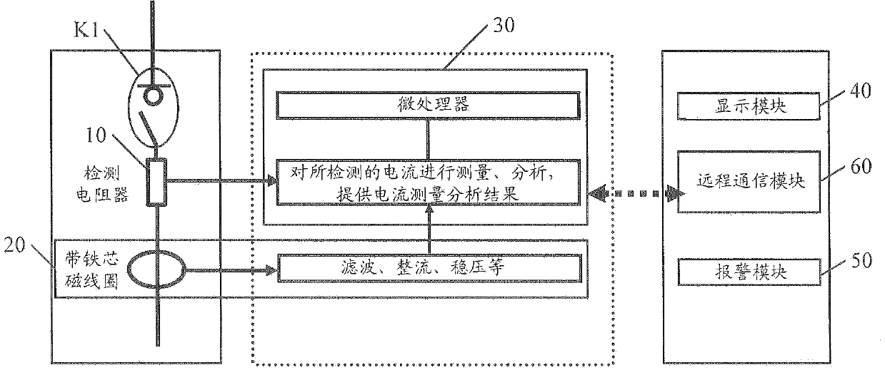
[0029] figure 2 is a block diagram of a single pole isolating switch according to the invention. exist figure 2 The block diagram on the left is the main circuit of the single-pole isolating switch, switch K1 repr...


PUM


Abstract

Disclosed is a multifunctional isolating switch comprising a mechanical switch structure component, a loop current detecting unit (10), an auxiliary power generating unit (20), a processor unit (30) and a display module (40). The loop current detecting unit (10) is used for detecting the current of a main power supply loop; the auxiliary power generating unit (20) is used for supplying auxiliary power for a switch body; the power of the processor unit (30) is supplied through the auxiliary power generated by the auxiliary power generating unit (20), and the processor unit (30) receives the detected current of the loop current detecting unit (10), measures and analyzes the detected current, provides the current measurement analysis result and provides display information according to the current measurement analysis result; the display module (40) receives display information from the processor unit (30) and displays the corresponded current value according to the received display information.

Description

technical field [0001] The present invention relates to isolating switches. Specifically, it relates to an isolating switch with multiple functions, such as one or more of current detection function, monitoring control function, digital display function and communication function. Background technique [0002] The isolating switch is generally located at the position of the main switch of the terminal power distribution, and has the function of making and breaking the current. At present, the common isolating switches in the market are just a device for mechanically switching on and off the current, and generally only have the functions of current switching and breaking. The current information flowing through the switch is not detected. [0003] However, with the development of the smart grid and the improvement of the technology of the electrical equipment, it is often necessary to know the power supply status information. [0004] For example, in civilian applications,...

Claims


Application Information

Patent Timeline
Patent Type & Authority Applications(China)
IPC IPC(8): H01H9/16G01R19/00
Inventor 余刚阮晓波周焱徐劲琳曹仁军
Owner SCHNEIDER ELECTRIC IND SAS
Why Eureka
Try Eureka