One-by-one bi-directional feeding device for PCBs

A two-way feeding, one-by-one technology, applied in the direction of thin material processing, object separation, pile separation, etc., can solve the problems of single function, high manufacturing cost, failure of PCB board feeding, etc., to avoid mutual friction and feed stability High and reduce the effect of input cost

Active Publication Date: 2014-08-20
海宁经开产业园区开发建设有限公司
View PDF6 Cites 5 Cited by
  • Summary
  • Abstract
  • Description
  • Claims
  • Application Information

AI Technical Summary

Problems solved by technology

Although there are independent supporting equipment related to SMT production lines such as automatic board feeding machine, board receiving machine, board storage machine and connecting table on the market, their functions are single and the volume is large, and customers need to plan a large space for placement , and it is necessary to purchase multiple devices with different functions to meet production needs, which lacks flexibility in actual production applications
[0003] In addition, the existing PCB board one-by-one feeding equipment generally adopts the structure of the material box and the manipulator. The structure is relatively complicated and the manufacturing cost is relatively high. It is difficult for the general conventional production line to bear such a high cost. There are also baffles and conveyor belts on the market. However, the separation of PCB boards depends on the friction between the PCB board and the conveyor belt. At the same time, adjacent PCB boards will also rub against each other, causing the PCB board to damage the circuit due to friction, or the PCB board The friction between the conveyor belt and the adjacent PCB boards is smaller than that between the adjacent PCB boards, resulting in the failure of PCB board feeding and obvious defects

Method used


Image

  • One-by-one bi-directional feeding device for PCBs
  • One-by-one bi-directional feeding device for PCBs
  • One-by-one bi-directional feeding device for PCBs

Examples


Embodiment Construction

[0023] In order to facilitate the understanding of those skilled in the art, the present invention will be further described below in conjunction with the embodiments and accompanying drawings, and the contents mentioned in the embodiments are not intended to limit the present invention.

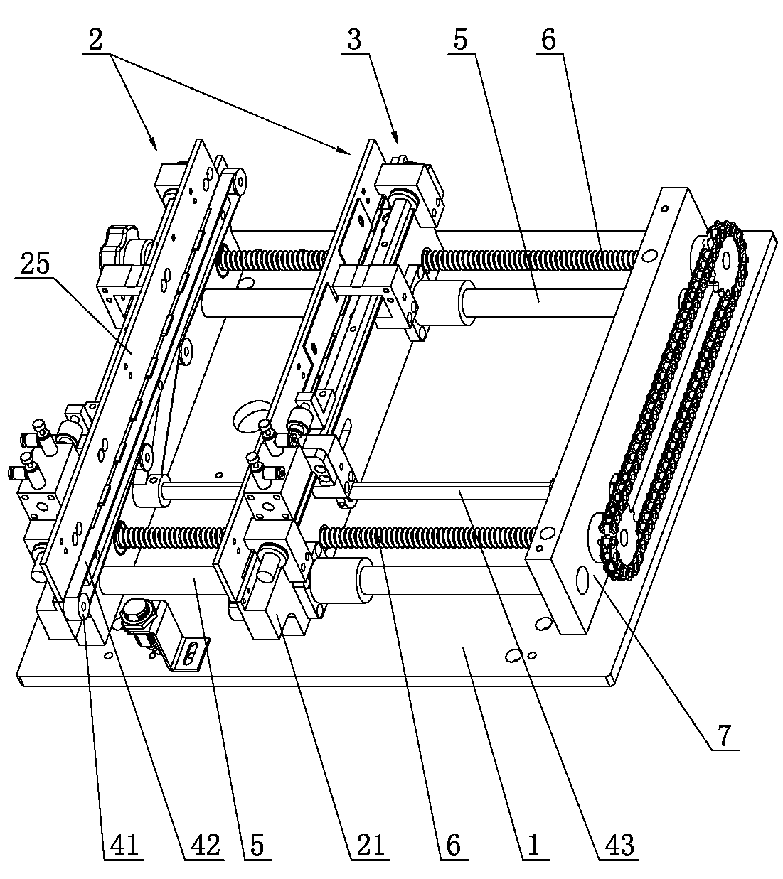
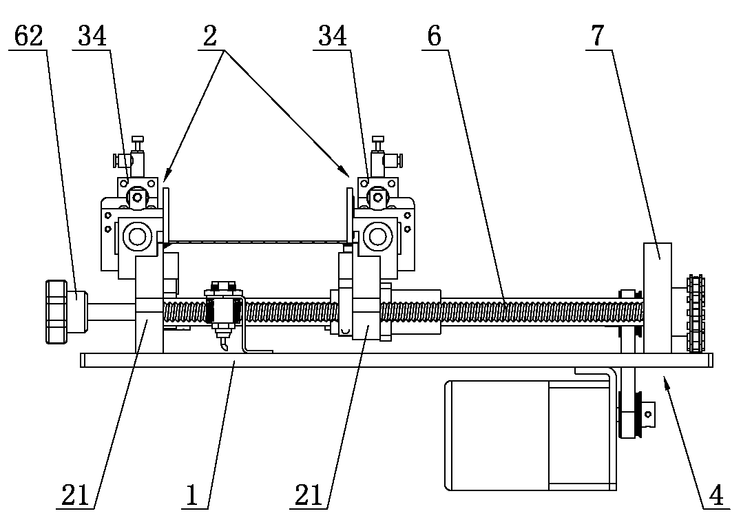
[0024] Such as Figure 1 to Figure 6 As shown, a PCB light board one by one two-way feeding equipment, including a substrate 1 and two sub-board components 2, the two sub-board components 2 are symmetrically installed on the substrate 1, and the sub-board components 2 include The mounting plate 21 of the substrate 1, the inner side of the mounting plate 21 is provided with a plurality of supporting plates 22 at intervals, the upper edge of the mounting plate 21 is equipped with a push plate 24 and a sub-plate for driving the push plate 24 to move back and forth Drive mechanism 3, the push plate 24 is provided with a plurality of protruding teeth 23, each of which protruding teeth 23 is locat...


PUM


Abstract

The invention relates to the technical field of PCB assembly, in particular to a one-by-one bi-directional feeding device for PCBs. The one-by-one bi-directional feeding device comprises a base plate and two board separating assemblies. Each board separating assembly comprises an installation plate installed on the base plate, and multiple board supporting blocks are arranged on the inner sides of the installation plates at intervals. A pushing plate and a board separation driving mechanism are installed on the upper edge of each installation plate. The pushing plates are provided with multiple extending teeth, and each extending tooth is located in the interval between every two adjacent board supporting blocks. Conveying assemblies are installed on the inner sides of the installation plates and lower than the bearing faces of the board supporting blocks, and baffles are arranged above the board supporting blocks. The bi-directional feeding device can be used for feeding materials to two different machining devices through bi-directional feeding, so that investment cost for a production line is greatly reduced; feeding stability is high, mutual friction between the adjacent PCBs can be effectively avoided, the rejection rate of electronic products is effectively decreased, and practicability is high.

Description

technical field [0001] The invention relates to the technical field of PCB board assembly, in particular to a PCB board-by-bidirectional feeding device. Background technique [0002] With the rapid development of electronic technology, the use of electronic products is becoming more and more extensive. PCB circuit boards are important components of electronic products, and most PCB circuit boards are completed through SMT production lines. Although there are independent supporting equipment related to SMT production lines such as automatic board feeding machine, board receiving machine, board storage machine and connecting table on the market, their functions are single and the volume is large, and customers need to plan a large space for placement , and it is necessary to purchase multiple devices with different functions to meet production needs, which lacks flexibility in actual production applications. [0003] In addition, the existing PCB board one-by-one feeding equi...

Claims


Application Information

Patent Timeline
Patent Type & Authority Applications(China)
IPC IPC(8): B65H3/24
Inventor 高喜宏林关洪曾翔清陈卓标
Owner 海宁经开产业园区开发建设有限公司
Why Eureka
Try Eureka