
Direction lever angle adjusting device

A technology of an angle adjustment device and a direction rod, which is used in cleaning methods, road cleaning, machine parts, etc., can solve the problems of time-consuming, laborious and unsanitary adjustment of the direction rod of the mopping machine.

Inactive Publication Date: 2014-03-26
WUHU AIRUITE ENVIRONMENTAL TECH
View PDF6 Cites 0 Cited by
  • Summary
  • Abstract
  • Description
  • Claims
  • Application Information

AI Technical Summary

Problems solved by technology

[0003] The technical problem to be solved by the present invention is that the adjustment of the direction bar of the existing mopping machine is time-consuming and laborious, and it is not hygienic

Method used


Image

  • Direction lever angle adjusting device

Examples


Embodiment Construction

[0008] The preferred technical solutions of the present invention will be described in detail below in conjunction with the accompanying drawings.

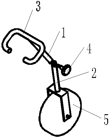
[0009] As shown in the figure, the steering rod angle adjustment device of the present invention includes a direction up shaft 1, a direction down shaft 2, a direction handle 3 and a steering wheel 5, and the direction handle 3 is fixed on the upper end of the direction shaft 1, so The steering wheel 5 is connected to the lower end of the lower shaft 2 in the direction, and the steering wheel 5 rotates around its own central axis. The upper shaft 1 in the direction and the lower shaft 2 in the direction are fixedly connected by a set nut 4. One of the holes fixedly connected with the set nut 4 on the shaft 1 and the lower shaft 2 is a through hole, and the other is a threaded hole.

[0010] When installing the set nut, first pass through the through hole, and then screw into the threaded hole to fix it. When it is necessary to adj...


PUM


Abstract

The invention discloses a direction lever angle adjusting device which comprises an upper direction shaft, a lower direction shaft, a direction handle and a steering wheel. The direction handle is fixed at the upper end of the upper direction shaft, the steering wheel is connected to the lower end of the lower direction shaft, the steering wheel rotates around a center axis thereof, the upper direction shaft and the lower direction shaft are fixedly connected through a set nut, and holes, fixedly connected with the set nut, in the upper direction shaft and the lower direction shaft are a through hole and a threaded hole. The direction lever angle adjusting device is timesaving, laborsaving, convenient and practical, the set nut is next to the direction handle, a user can reach to the set nut only by reaching out hands, and after the set nut is unscrewed, the angle of a direction lever can be adjusted easily by lightly rotating the direction handle.

Description

technical field [0001] The invention relates to a device for adjusting the angle of a direction bar on a floor mopping machine. Background technique [0002] The mopping machine is suitable for mopping and sweeping in residential areas, hotels, factories, stations, airports, hotels and other places. Because of the advantages of relatively clean mopping and labor saving, it is becoming more and more popular among people. In the past, when the mopping vehicle was adjusting the steering rod, people often clamped the front drive device with their legs and used a lot of force or used a wrench to complete the angle adjustment of the steering rod, which was unhygienic, laborious and time-consuming. Contents of the invention [0003] The technical problem to be solved by the present invention is that the adjustment of the direction bar of the existing mopping machine is time-consuming and laborious, and it is also unhygienic. [0004] In order to solve the above-mentioned ...

Claims


Application Information

Patent Timeline
Patent Type & Authority Applications(China)
IPC IPC(8): E01H1/00A47L11/40
Inventor 艾和金杨金树朱家旺王家梅邵和胜
Owner WUHU AIRUITE ENVIRONMENTAL TECH
Learn More