
Femoral Ring Triangle Synchronous Control Extender

A synchronous control and extender technology, applied in the field of femoral extenders, can solve problems such as complex shortening deformity of limbs, increased soft tissue tension across joints, and disturbance of joint dynamic balance, so as to avoid articular cartilage degeneration, Avoid knee dislocation and achieve the effect of reconstruction

Active Publication Date: 2015-09-09
JIANGSU GUANGJI MEDICAL TECH
View PDF10 Cites 0 Cited by
  • Summary
  • Abstract
  • Description
  • Claims
  • Application Information

AI Technical Summary

Problems solved by technology

However, the disadvantage of the above-mentioned femoral extender is that usually it can only stretch the bone without crossing the joint, and it cannot stretch and extend the soft tissues such as muscles, nerves, and blood vessels crossing the knee joint synchronously. When performing cross-joint femur lengthening, the use of existing bone extenders for cross-joint traction is prone to serious complications of limb lengthening such as nonunion, joint dislocation, and knee joint dysfunction
In limb lengthening technology, although standardizing the principle of bone lengthening technology can solve the treatment needs of some limb shortening deformities, it is difficult to solve the clinical difficulties caused by complex limb shortening deformities and large limb shortening deformities
Because the traditional bone extender cannot provide direct force to soft tissues such as muscles across the joint, its force can only be transmitted indirectly through the joint; as the length of the bone continues to grow, it will inevitably cause the tension of the soft tissue across the joint to increase, thereby inducing Corresponding disturbance of joint homeostasis, which may even lead to joint dislocation or cartilage damage

Method used


Image

  • Femoral Ring Triangle Synchronous Control Extender
  • Femoral Ring Triangle Synchronous Control Extender
  • Femoral Ring Triangle Synchronous Control Extender

Examples


Embodiment Construction

[0054] The present invention will be further described in detail below in conjunction with test examples and specific embodiments. However, it should not be understood that the scope of the above subject matter of the present invention is limited to the following embodiments, and all technologies realized based on the content of the present invention belong to the scope of the present invention.

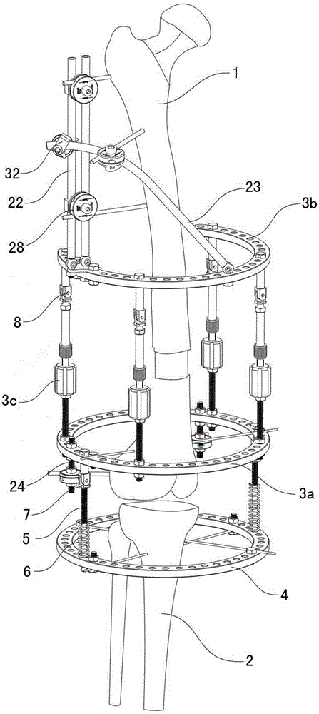
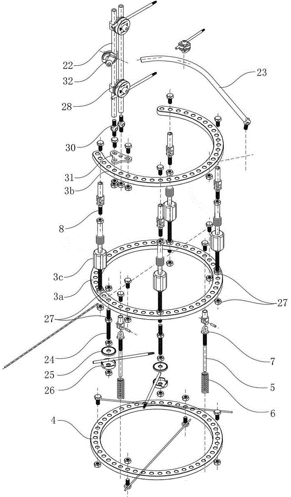
[0055] Example Figure 2 to Figure 10 As shown, this femoral ring type triangular synchronous control extender is composed of an extender frame, a steel needle fixing clip 28 connected to the extender frame, and a steel needle clamped in the steel needle fixing clip.

[0056] Described extender frame body comprises the femoral extender frame body that is arranged on femur 1 place, and femoral extender frame body comprises femoral hole ring 3a, is arranged on femur upper hole ring 3b above the femoral hole ring 3a top, and is connected on the femur. Several fast stretch extension rod...


PUM


Abstract

A ring type triangular synchronous control extender for the thighbone is composed of an extender frame body, a steel needle fixing clamp connected to the extender frame body and a steel needle clamped in the steel needle fixing clamp. The extender frame body comprises a thighbone extender frame body arranged at the thighbone position. The thighbone extender frame body comprises a thighbone low hole ring, a thighbone upper hole ring arranged above the thighbone lower hole ring and a plurality of quick traction extension rods connected between the thighbone lower hole ring and the thighbone upper hole ring. The thighbone extender frame body further comprises one tubular connection rod or two tubular connection rods connected above the thighbone upper hole ring and an arc bow connected between the tubular connection rod and the thighbone upper hole ring. The extender frame body further comprises a tibia hole ring arranged at the tibia position and an elastic traction fixing rod arranged between the thighbone lower hole ring and the tibia hole ring. The extender can dynamically compensate pressure on the knee to enable the pressure on the knee to be dynamically balanced and can enable the knee to have certain mobility in an extension process.

Description

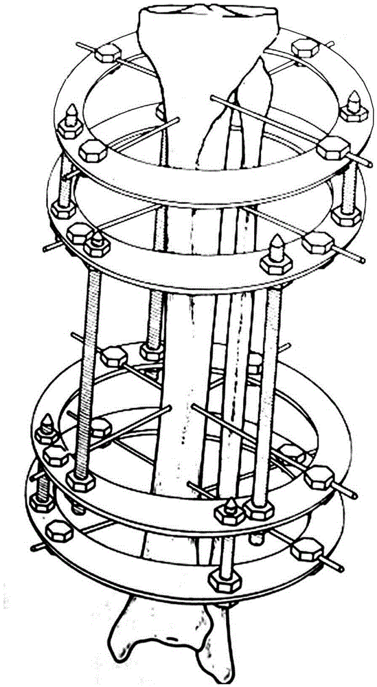
technical field [0001] The invention relates to a bone external fixator, in particular to a femur extender. Background technique [0002] The concept of bone lengthening originates from the original callus lengthening, which means that steel needles are placed at both ends of the osteotomy, and bone lengthening is applied to the bone to increase the length of the bone. Based on the concept that bone lengthening can also moderately increase the length of limbs, bone lengthening is a passive method of limb lengthening. Existing bone extenders, such as figure 1 The shown Ilizarov ring-type extender, when performing femur lengthening surgery, needles are passed through the femur and tibia respectively, and the bone is lengthened or shortened on the axis. However, the disadvantage of the above-mentioned femoral extender is that usually it can only stretch the bone without crossing the joint, and it cannot stretch and extend the soft tissues such as muscles, nerves, and blood ve...

Claims


Application Information

Patent Timeline
Patent Type & Authority Patents(China)
IPC IPC(8): A61B17/62
Inventor 夏和桃李刚彭爱民夏洪菁王坤正刘利民
Owner JIANGSU GUANGJI MEDICAL TECH
Learn More