Adjacent boundary length deducing method and device
A technology of boundary length and export device, applied in the field of video coding and decoding, can solve problems such as increasing memory overhead, and achieve the effect of improving video coding efficiency
- Summary
- Abstract
- Description
- Claims
- Application Information
AI Technical Summary
Problems solved by technology
Method used
Image
Examples
Embodiment 1
[0029] figure 1 is a schematic diagram of the current pixel block and its adjacent pixel blocks in the spatial domain.
[0030] This example provides a method for deriving the adjacent boundary length of inter-frame prediction blocks in video encoding and decoding, including:
[0031] Step 1, at least two adjacent blocks of the current pixel block are obtained.
[0032] Specifically, such as figure 1 As shown, the adjacent blocks in the spatial domain of the current pixel block include A1, A2, . . . , AN, B1, B2, ... BM, and N and M are natural numbers greater than 0. Among them, K blocks are inter-frame prediction blocks, 0≤K≤N+M. The motion information of the block in the same direction as the reference frame of the current pixel block among the K inter-frame prediction blocks is stored in the input device.
[0033] Step 2: Merge adjacent blocks whose adjacent blocks are continuous and whose prediction information is consistent into one adjacent unit.
[0034] Specifica...
Embodiment 2
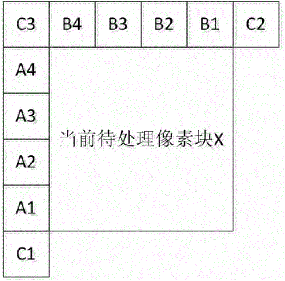
[0040] figure 2 It is a schematic diagram of a current pixel block and its adjacent motion vector storage units in the space domain.
[0041] This example provides a method for deriving adjacent boundaries of inter-frame prediction blocks in video encoding and decoding, including:
[0042] Step 1, at least two adjacent blocks of the current pixel block are obtained.
[0043] Specifically, such as figure 2 As shown, there are A1-A4, B1-B4 and C1-C3 motion vector storage units around the current pixel block. These motion vector storage units are said adjacent blocks. First obtain the motion vectors in these motion vector storage units.
[0044]Step 2: Merge adjacent blocks whose adjacent blocks are continuous and whose prediction information is consistent into one adjacent unit.
[0045] Specifically, after obtaining a plurality of adjacent blocks in step 1, check whether the blocks in A1-A4 are consecutive blocks with the same motion vector, and fuse the consecutive bloc...
Embodiment 3
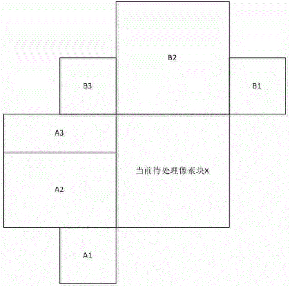
[0051] image 3 is a schematic diagram of a current pixel block and its adjacent blocks in the spatial domain.
[0052] This example provides a method for deriving adjacent boundaries of inter-frame prediction blocks in video encoding and decoding, including:
[0053] Step 1, at least two adjacent blocks of the current pixel block are obtained.
[0054] Specifically, such as image 3 As shown, there are 6 adjacent blocks A1, A2, A3, B1, B2, and B3 around the current pixel block. Motion vectors in these neighboring blocks are obtained first.
[0055] Step 2: Merge adjacent blocks whose adjacent blocks are continuous and whose prediction information is consistent into one adjacent unit.
[0056] Specifically, a possible implementation method is to compare whether the motion vectors in consecutive adjacent blocks in A1, A2, and A3 are the same, compare whether the motion vectors in consecutive adjacent blocks in B1, B2, and B3 are the same, and if any If the motion vectors o...
PUM
 Abstract
Description
Claims
Application Information
 - R&D
- Intellectual Property
- Life Sciences
- Materials
- Tech Scout
- Unparalleled Data Quality
- Higher Quality Content
- 60% Fewer Hallucinations
Browse by: Latest US Patents, China's latest patents, Technical Efficacy Thesaurus, Application Domain, Technology Topic, Popular Technical Reports.
© 2025 PatSnap. All rights reserved.Legal|Privacy policy|Modern Slavery Act Transparency Statement|Sitemap|About US| Contact US: help@patsnap.com


