Circuit for eliminating shutdown ghost shadows and array substrate
A power-off afterimage and array substrate technology, which is applied to static indicators, instruments, etc., can solve the problems that the charge cannot be released immediately and the image remains.
- Summary
- Abstract
- Description
- Claims
- Application Information
AI Technical Summary
Problems solved by technology
Method used
Image
Examples
Embodiment 1
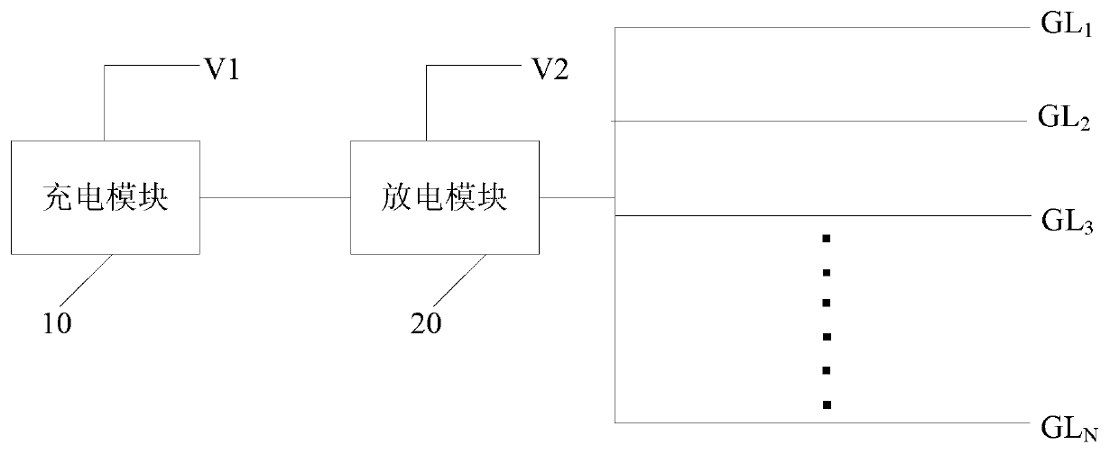
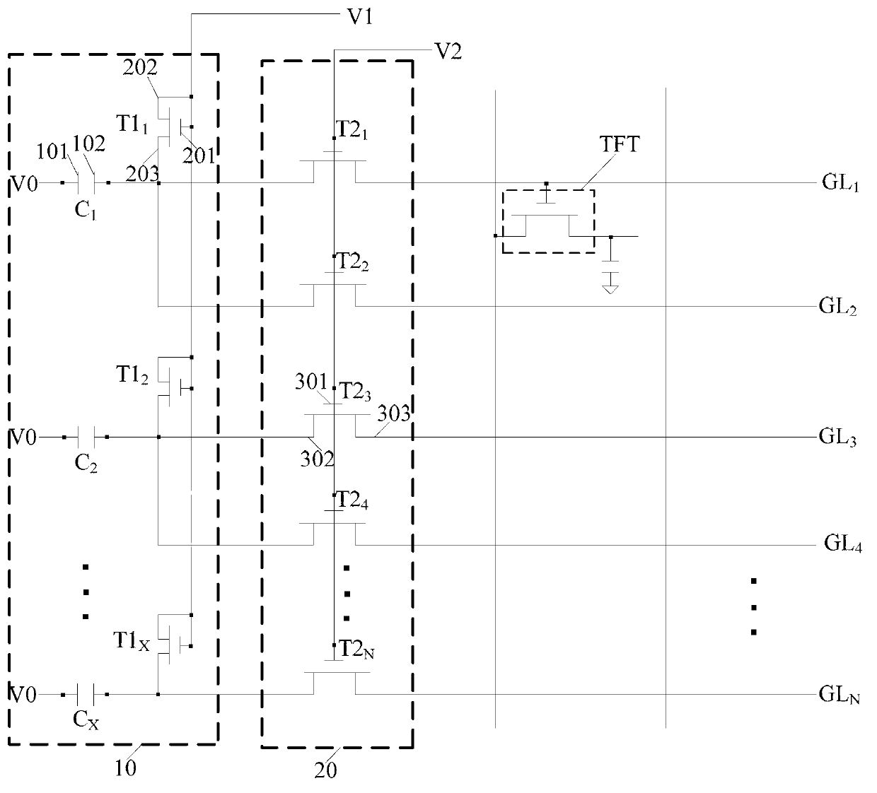
[0050] The embodiment of the present invention provides a circuit for eliminating afterimage after shutdown, such as image 3 As shown, the circuit includes: multiple capacitors C 1 、C 2 …C X , a plurality of first switch units T1 1 , T1 2 …T1 X , and a plurality of second switch units T2 1 , T2 2 , T2 3 , T2 4 …T2 N ; N is the number of grid lines, and X is a positive integer smaller than N.
[0051] Wherein, each capacitor includes: a first electrode 101 and a second electrode 102, and the first electrode 101 of the capacitor is connected to the reference voltage terminal V0.
[0052] Each of the first switch units includes: a first control terminal 201, a first input terminal 202, and a first output terminal 203; the first output terminal 203 of the first switch unit is connected to the second electrode 102 of the capacitor, so The first control terminal 201 and the first input terminal 202 of the first switch unit are connected to the first voltage terminal V1. ...
Embodiment 2
[0068] The embodiment of the present invention provides a circuit for eliminating afterimage after shutdown, such as Figure 5 As shown, the circuit includes: multiple capacitors C 1 、C 2 …C i …C N , a plurality of first switching units T1 1 , T1 2 …T1 i …T1 N , a plurality of second switching units T2 1 , T2 2 …T2 i …T2 N , and a plurality of third switching units T3 1 , T3 2 …T3 i …T3 N-1 ; N is the number of grid lines, and i is an integer greater than 1 and less than N.
[0069] Each capacitor C i It includes: a first electrode 101 and a second electrode 102, the first electrode 101 of the capacitor is connected to the reference voltage terminal V0.
[0070] Each first switch unit T1 i It includes: a first control terminal 201 , a first input terminal 202 and a first output terminal 203 . Specifically, the first first switch unit T1 1 The first control terminal 201 and the first input terminal 202 are connected to the first voltage terminal V1, and the f...
PUM
 Abstract
Description
Claims
Application Information
 - R&D
- Intellectual Property
- Life Sciences
- Materials
- Tech Scout
- Unparalleled Data Quality
- Higher Quality Content
- 60% Fewer Hallucinations
Browse by: Latest US Patents, China's latest patents, Technical Efficacy Thesaurus, Application Domain, Technology Topic, Popular Technical Reports.
© 2025 PatSnap. All rights reserved.Legal|Privacy policy|Modern Slavery Act Transparency Statement|Sitemap|About US| Contact US: help@patsnap.com


