Collapsible pushchair

A stroller and frame technology, applied in the field of foldable strollers, can solve the problems of dirty footrests, damaged shoes, etc.

Inactive Publication Date: 2013-03-20
MAXI MILIAAN BV
View PDF4 Cites 6 Cited by
  • Summary
  • Abstract
  • Description
  • Claims
  • Application Information

AI Technical Summary

Problems solved by technology

[0003] The disadvantage of pulling the footrest by hand is that the footrest can become soiled by shoes that were previously placed on the footrest for a second movement
However, the disadvantage of pulling through the upper side of the shoe at the footrest is that the upper side of the shoe will be damaged

Method used


Image

  • Collapsible pushchair
  • Collapsible pushchair
  • Collapsible pushchair

Examples


Embodiment Construction

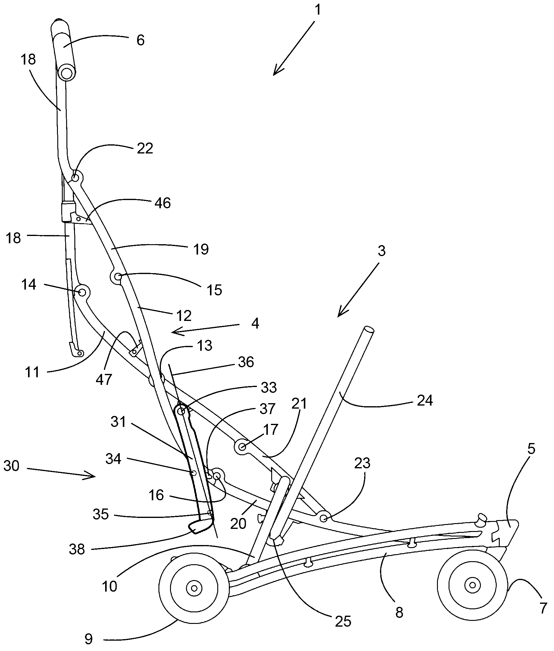
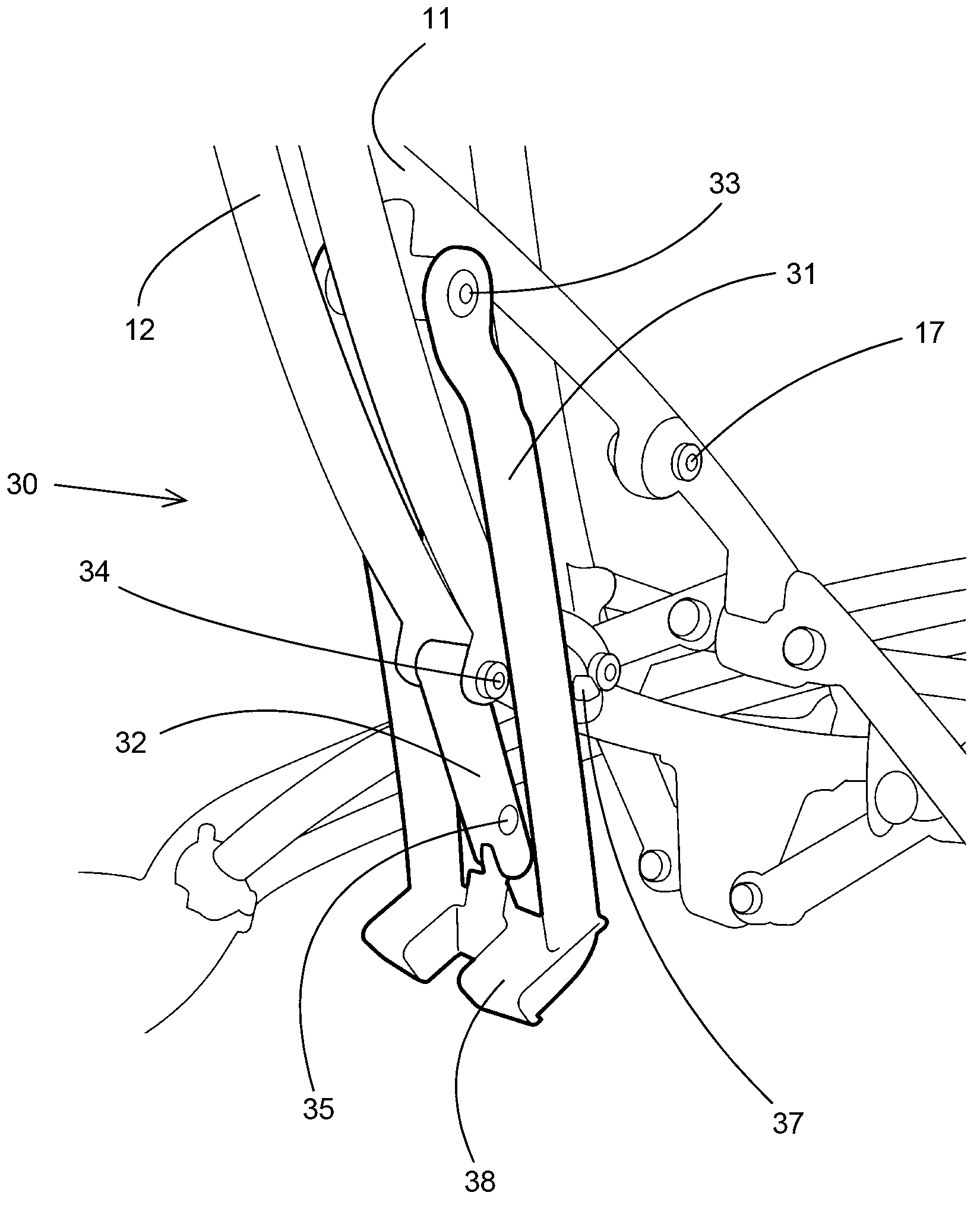
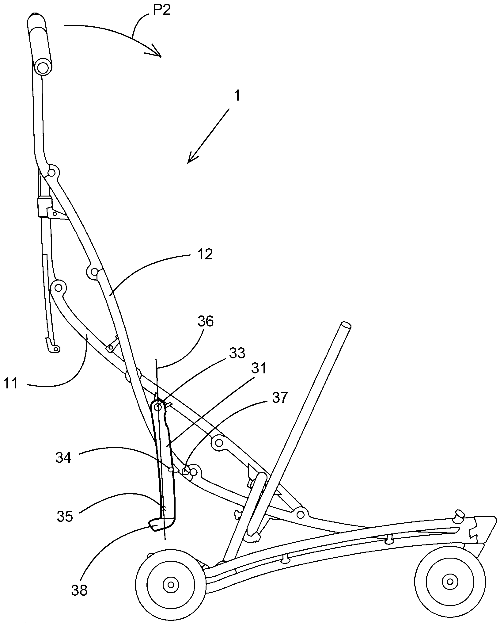
[0038] Figure 1A-6 Different views of an embodiment of the collapsible stroller according to the invention are shown.

[0039] The stroller 1 comprises a frame 3 provided with an elongated spine 4 . The spine 4 is curved to define a seat cavity within the frame 3 in which a flexible seat member (not shown) may be placed.

[0040] Spine 4 is fixedly coupled at one end to coupler 5 and at its other end to handle assembly 6 .

[0041] The frame 3 includes wheels 7 mounted on the underside of the coupler 5 to provide ground engaging support beneath the coupler 5 when the frame 3 is used in its upright configuration.

[0042] The frame 3 also includes a pair of support arms 8 extending from the coupling 5 . Each support arm 8 carries a wheel 9 at one end and is pivotally coupled to the coupling 5 at its other end.

[0043] In the vertical form of frame 3, such as Figure 1A As shown, the support arm 8 is positioned relative to the coupler 5 to space the wheels 9 from each othe...


PUM


Abstract

A collapsible pushchair comprising at least a frame provided with at least two rods being pivotally connected to each other, which frame is foldable from an erect configuration to a collapsed configuration and vice versa, wherein the frame is also provided with a lock to lock the frame in its erect configuration. The lock comprises at least two members, wherein a first member is swivelably connected at a first swivel to the first rod, a second member is swivelably connected at a second swivel to the second rod, and the first and second members are pivotally connected to each other at a distance from the first and second swivel at a pivot, wherein the second swivel is movable from a first position wherein the second swivel is located on one side of a virtual line through the pivot and the first swivel, in which first position the frame is locked in its erect configuration, via an intermediate position wherein the second swivel is located between the pivot and first swivel on the virtual line (36), to a second position wherein the second swivel is located on the other side of the virtual line (36), in which second position the frame is unlocked, and / or vice versa.

Description

technical field [0001] The present invention relates to a collapsible stroller comprising at least one frame provided with at least two bars pivotally connected to each other, the frame being collapsible from an upright configuration to a collapsed configuration and vice versa , wherein the frame is also provided with a locking device to lock the frame in its upright configuration, the locking device comprising at least two members, wherein the first member is rotatably connected to the first rod at the first swivel, the second member Rotatably connected to the second lever at the second swivel, and the first member and the second member are pivotally connected to each other at a pivot at a distance from the first swivel and the second swivel, wherein the second The swivel is movable from a first position via an intermediate position to a second position, and / or vice versa, in which the second swivel is on one side of an imaginary line passing through the pivot and the first s...

Claims


Application Information

Patent Timeline
Patent Type & Authority Applications(China)
IPC IPC(8): B62B7/06
CPCB62B2205/24B62B2205/02B62B7/004B62B2205/23B62B7/10B62B2205/06
Inventor 盖尔亚安·施托姆皮特鲁斯·亨利库斯·玛利亚·斯托克曼约翰·格特·蒂尔·范戴克
Owner MAXI MILIAAN BV
Why Eureka
Try Eureka