
Light-emitting device

A technology for light-emitting devices and light-emitting devices, which is applied in the direction of electrical components, electric solid-state devices, circuits, etc., and can solve problems such as non-compliant backlighting

Inactive Publication Date: 2013-03-06
HONG FU JIN PRECISION IND (SHENZHEN) CO LTD +1
View PDF6 Cites 16 Cited by
  • Summary
  • Abstract
  • Description
  • Claims
  • Application Information

AI Technical Summary

Problems solved by technology

However, the color temperature range (2300K~9000K) of white LEDs used for general lighting is only half or even a quarter of the color temperature range (8000K~15000K) of white LEDs for backlighting, which does not meet the requirements of backlighting

Method used


Image

  • Light-emitting device
  • Light-emitting device
  • Light-emitting device

Examples


Embodiment Construction

[0015] The present invention will be further described in detail below in conjunction with the accompanying drawings.

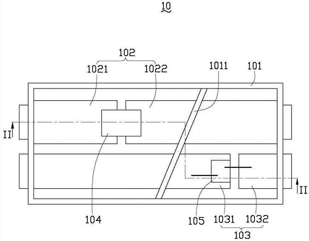
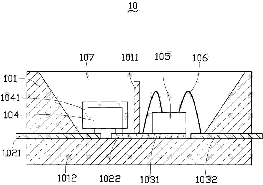
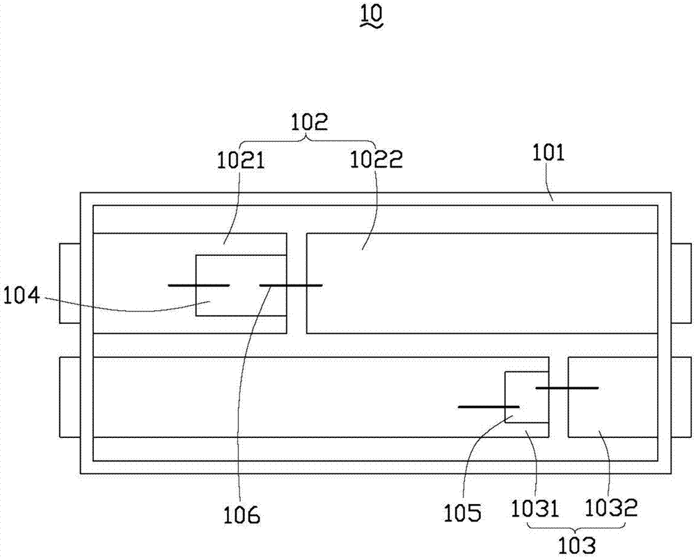
[0016] see Figure 1-2 , shows a top view and a cross-sectional view along line II-II of the light emitting device 10 according to the first embodiment of the present invention. In this embodiment, the light emitting device 10 includes a reflective cup 101 , a substrate 1012 , two conductive plates 102 , 103 , a first light emitting device 104 , a second light emitting device 105 , several wires 106 and a package 107 .

[0017] The substrate 1012 has a first surface and a second surface opposite to the first surface. Two conductive plates 102 and 103 are disposed on the first surface of the substrate 1012 . The conductive plates 102 , 103 are strip-shaped, and both are divided into first electrodes 1021 , 1031 and second electrodes 1022 , 1032 insulated from each other by openings. The first light emitting device 104 is mounted on the conductive plate 102 ...


PUM


Abstract

A light-emitting device comprises a substrate and a first light emitter emitting white light. The substrate comprises a first surface and a second surface opposite to the first surface. The first light emitter is disposed on the first surface of the substrate. A second light emitter emitting red light is also disposed on the first surface of the substrate. Color temperature of the light emitted by the second light emitter is higher than that of the light emitted by the first light emitter. High color temperature colored light emitted by the second light emitter mixes with low color temperature colored light emitted by the first emitter, so that mixed light emitted by the light-emitting device has large color temperature range. The low color temperature light emitter is compensated by the high color temperature light emitter, so that the light-emitting device which is satisfactory is made. The light-emitting device meets the color temperature requirement when serving as a backlight of a liquid crystal display panel.

Description

technical field [0001] The invention relates to a light emitting device, in particular to a light emitting device used as a backlight light source. Background technique [0002] With the continuous development of light-emitting diodes (LEDs), the traditional method of using cold cathode fluorescent lamps (CCFLs) as backlighting for color LCDs has been gradually replaced by LED backlighting. At present, the production technology of white light LED used in lighting is relatively mature, and the color temperature of the light emitted by it is higher than that of other lighting devices. However, the color temperature range (2300K~9000K) of white LEDs used for general lighting is only half or even a quarter of the color temperature range (8000K~15000K) of white LEDs for backlighting, which does not meet the requirements of backlighting. Since the general lighting market will be much larger than the backlighting market in the future, there is an urgent need for a solution to make...

Claims


Application Information

Patent Timeline
Patent Type & Authority Applications(China)
IPC IPC(8): H01L25/075H01L33/48H01L33/62
CPCH01L2224/16245H01L2224/48247H01L2224/48257
Inventor 曾坚信
Owner HONG FU JIN PRECISION IND (SHENZHEN) CO LTD
Learn More