High-pressure multiphase fluid density measurement device and measurement and calculation method thereof
A multi-phase fluid and density measurement technology, which is applied to determine the direction of specific gravity and material inspection products by using the flow characteristics of the fluid, can solve the problems that are difficult to realize and the measurement workload is unbearable, and achieve easy operation, rigorous test principle, and test The effect of simple method
- Summary
- Abstract
- Description
- Claims
- Application Information
AI Technical Summary
Problems solved by technology
Method used
Image

Examples
Embodiment approach 1
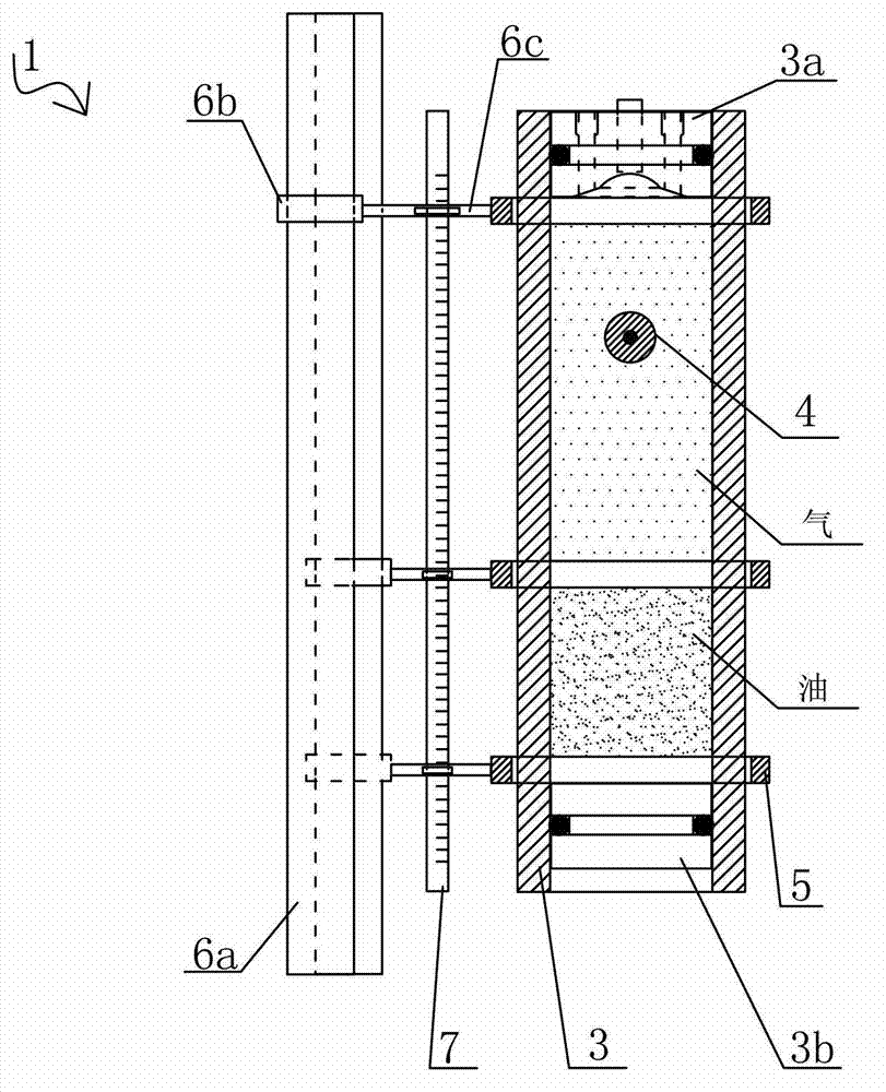
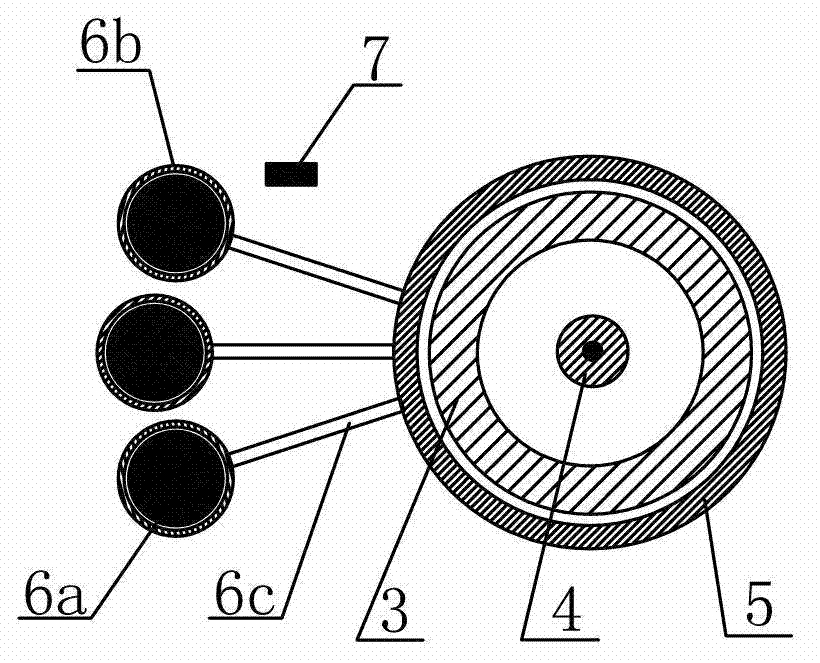
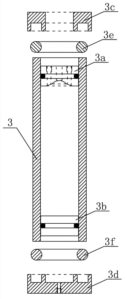
[0100] Such as Figure 1 to Figure 11As shown, the embodiment of the present invention proposes a high-pressure multiphase fluid density measuring device, which includes an inner model 1 and an outer model 2 , and the inner model 1 is set inside the outer model 2 . The inner model 1 includes an analysis cylinder 3 , a test ball 4 , an induction coil 5 and a scale 7 . The upper and lower parts of the analysis cylinder 3 are respectively provided with a top piston 3a and a bottom piston 3b, the top piston 3a is provided with a magnet hole 3a1 for placing an electromagnet, and the top piston 3a is axially provided with a fluid through hole 3a2, through which the fluid passes The hole 3a2 is used to inject or empty the fluid in the analysis cylinder 3. Here, the magnet hole 3a1 is arranged in the middle of the top piston 3a, and there are two fluid through holes 3a2, which are respectively located on both sides of the magnet hole 3a1; the bottom piston 3b It can be moved up and d...
Embodiment approach 2
[0120] The embodiment of the present invention proposes a method for measuring and calculating the density of two-phase fluids and the mass transfer content of components under reservoir conditions. The method includes the steps of:
[0121] (1) Provide the high-pressure multiphase fluid density measuring device in embodiment 1, and carry out experimental preparation, known parameter (such as known mass and volume m 球 , V 球 ) test ball into the analysis cylinder, and install the inner model 1 and the outer model 2;
[0122] (2) Prepare the gas under the pressure P1 and temperature T1 conditions of known mass; prepare the liquid under the same conditions with known volume; both are contained in specific containers;
[0123] (3) Put the outer model 2 under the above-mentioned conditions of pressure P1 and temperature T1, and evacuate the upper part of the analysis cylinder 3, so that the bottom piston 3b is in contact with the test ball 4 and the top piston 3a. The pressure of...
Embodiment approach 3
[0137]This embodiment is about the filling device in Embodiment 2, and its specific description is as follows:
[0138] Such as Figure 14 to Figure 17B As shown, the filling device proposed by the embodiment of the present invention includes a pressure-resistant container 8 and a pushing part 9 . The pressure-resistant container 8 is composed of a container cylinder 8a, a piston 8b, a hollow plug 8c and a valve 8d for controlling the fluid in and out of the container cylinder 8a. The container cylinder 8a is a space for containing gas, the valve 8d is located outside the container cylinder 8a, and is connected to one end of the container cylinder 8a, and the hollow plug 8c is connected to the other end of the container cylinder 8a. The piston 8b is movably and sealedly connected in the container barrel 8a, that is, the piston 8b realizes the function of gas in and out by moving back and forth, and can adjust the gas pressure of the container barrel 8a. The pushing member 9 ...
PUM
| Property | Measurement | Unit |
|---|---|---|
| Outer diameter | aaaaa | aaaaa |
| Diameter | aaaaa | aaaaa |
Abstract
Description
Claims
Application Information
 - R&D
- Intellectual Property
- Life Sciences
- Materials
- Tech Scout
- Unparalleled Data Quality
- Higher Quality Content
- 60% Fewer Hallucinations
Browse by: Latest US Patents, China's latest patents, Technical Efficacy Thesaurus, Application Domain, Technology Topic, Popular Technical Reports.
© 2025 PatSnap. All rights reserved.Legal|Privacy policy|Modern Slavery Act Transparency Statement|Sitemap|About US| Contact US: help@patsnap.com