
System for motorising a wheel connected to a suspension

A technology of motorized and motion systems, applied in the field of motorized systems

Inactive Publication Date: 2012-09-05
MICHELIN & CO CIE GEN DES ESTAB MICHELIN +2
View PDF4 Cites 14 Cited by
  • Summary
  • Abstract
  • Description
  • Claims
  • Application Information

AI Technical Summary

Problems solved by technology

[0006] This system often has the disadvantage that the motor unit is embedded in the part covered by the belly of the aircraft and cannot be cooled by the surrounding air

Method used


Image

  • System for motorising a wheel connected to a suspension
  • System for motorising a wheel connected to a suspension
  • System for motorising a wheel connected to a suspension

Examples


Embodiment Construction

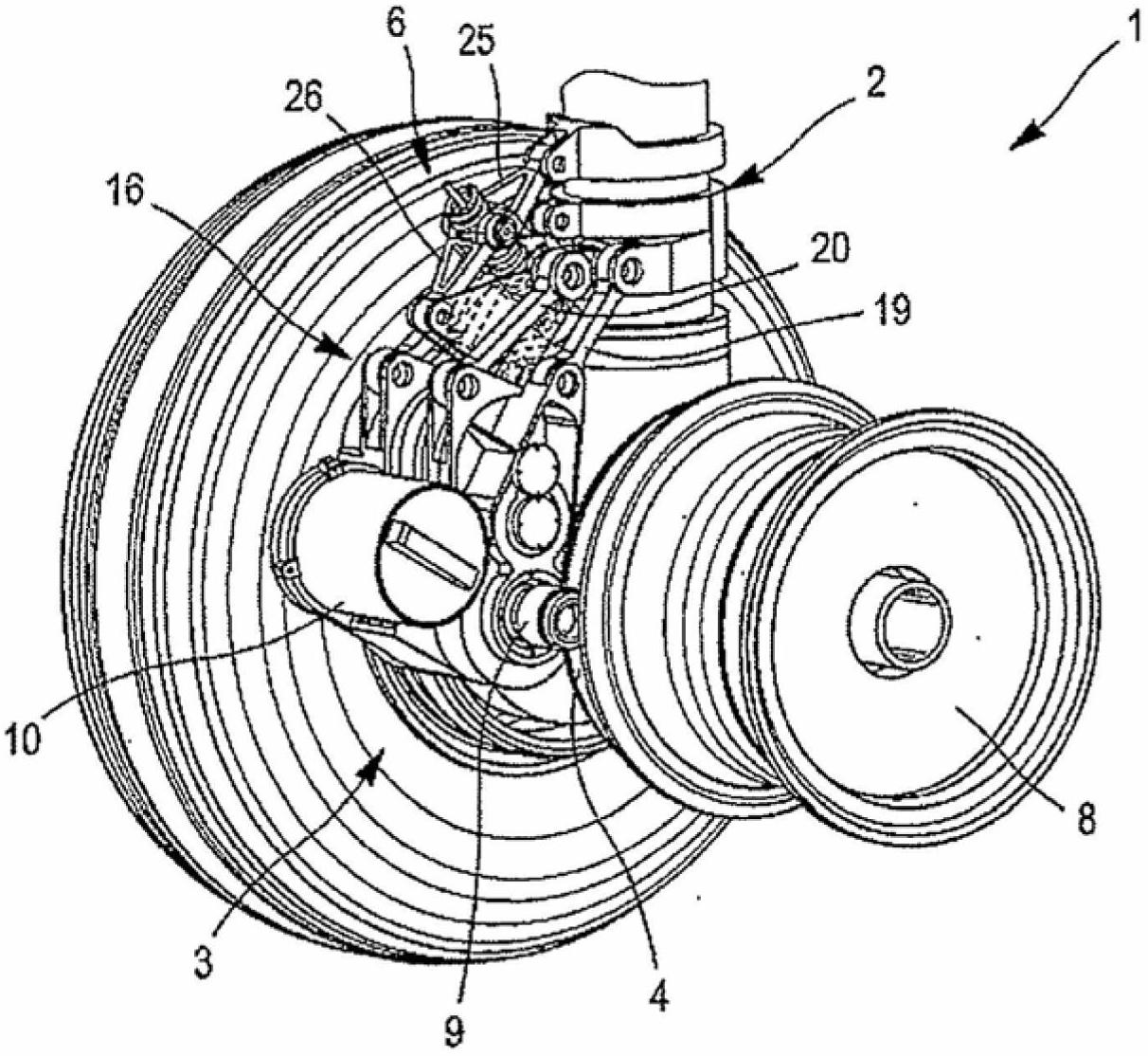
[0044] figure 1 The main landing gear 1 of the aircraft is depicted, one of the two wheels 5 of which is depicted without its tires for the sake of clarity. In addition to the coaxial two wheels 5 and the suspension strut 2 carrying them, the undercarriage 1 also comprises an assembly of two wheel motorization systems, ie one system for each wheel 5 . Having one motorized system per wheel 5 eliminates the need to incorporate a differential and allows the speed of the wheels 5 to adapt to the turn. It also allows the loads on the suspension and wheel motorization to be locally balanced. In addition, it distributes the load to all tires and thus makes tire wear even and limited.

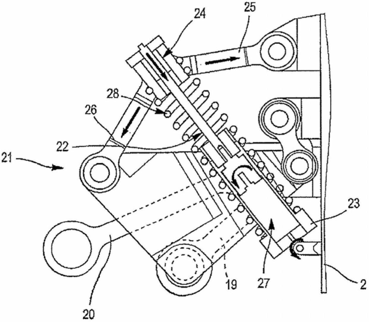
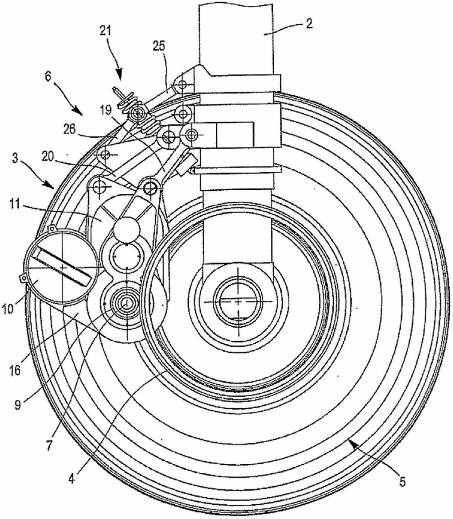
[0045] The motorized system according to the invention comprises a motor unit 3 carried by a sprung part 2a of a suspension strut 2 , a driver member 4 fixed to a wheel 5 and a clutch device 6 which The clutch device 6 allows a gear 9 to be connected to the drive member 4 , the gear 9 being fixed to...


PUM


Abstract

The invention relates to a system for motorising a wheel (5) connected to a suspension, the system including an engine block (3) and a driving member (4) secured to the wheel (5). According to the invention, the engine block is secured to the suspended portion of the MacPherson strut (2) and a clutch device (6) connects the output shaft (7) of the engine block (3) to the driving member (4).

Description

technical field [0001] The invention relates to a motorization system for powering wheels associated with a suspension for moving an aircraft around the ground. Background technique [0002] The concept of motorizing the movement of aircraft on the ground means motorizing aircraft so that they move automatically but at low speeds, similar to the behavior of airplanes before take-off or after landing at an airport; it is commonly known as " slide". So here it does not mean that the wheel is motorized in order to increase the speed of the wheel to coincide with the landing speed, as proposed in the prior art. [0003] A known motorized system for powering a wheel associated with a suspension is of the type comprising a motor unit and a drive member fixed to the wheel. [0004] However, such systems have a certain susceptibility to vibrations which can be particularly great and disruptive when traveling along the ground on which the vehicle carrying the motorized system is tr...

Claims


Application Information

Patent Timeline
Patent Type & Authority Applications(China)
IPC IPC(8): B64C25/40
CPCB64C25/405Y02T50/80
Inventor O·埃辛格C·斯塔基
Owner MICHELIN & CO CIE GEN DES ESTAB MICHELIN
Learn More