Tangential combustor

A technology of combustion section and combustion cylinder, which is applied in the direction of combustion chamber, combustion method, combustion equipment, etc., and can solve the problems of expensive repair and replacement, reduction of total mechanical pressure ratio, etc.

Inactive Publication Date: 2011-11-23
GENERAL ELECTRIC CO
View PDF8 Cites 9 Cited by
  • Summary
  • Abstract
  • Description
  • Claims
  • Application Information

AI Technical Summary

Problems solved by technology

To address these varying needs and operating conditions, first stage vanes and associated support structures and cooling systems have developed into complex systems that can be expensive to manufacture, install, and if damaged repair and replace
[0004] The first stage nozzle increases the total pressure drop by about 1.5%, thus reducing the overall pressure ratio of the machine

Method used


Image

  • Tangential combustor
  • Tangential combustor
  • Tangential combustor

Examples


Embodiment Construction

[0023] figure 1 A typical combustor for a gas turbine is shown, which includes a compressor, multiple combustors, and a turbine. The compressor pressurizes the inlet air, which then flows back into the combustor, where it is used to cool the combustor and provide air for the combustion process. The combustor 10 includes a liner 12 and a transition piece 14. The liner 12 defines a combustion zone. The transition piece 14 connects the outlet end of the combustor with the inlet end of the turbine so as to transfer the combustion products to the turbine. The interface between the combustor transition piece 14 and the first stage turbine nozzle requires the use of a seal to reduce leakage into the gas passage.

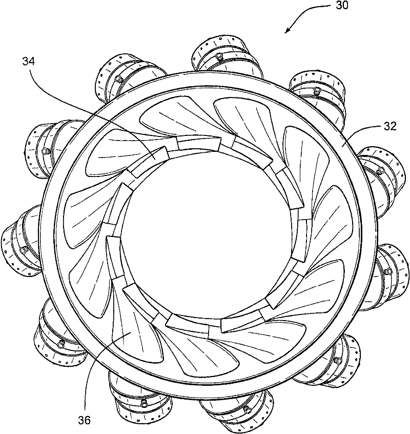
[0024] figure 2 It is an end view of the combustion section 30 for a gas turbine. The combustion section 30 includes a casing 32 that defines a chamber, and a plurality of combustion cylinders 34 arranged in the casing and oriented in an annular pattern as shown. A pluralit...


PUM


Abstract

The present invention relates to a tangential combustor, specifically to a combustion section for a gas turbine. The combustion section includes a casing (32)defining a chamber, a plurality of combustor cans (34)disposed in the casing and oriented in an annular pattern, and a plurality of transition pieces (36) each coupled with one of the combustor cans. The transition pieces direct products of combustion from the combustor cans into contact with rotating buckets of the gas turbine. Each of the transition pieces is angled in two planes to effect turning of the products of combustion and to shorten the gas turbine.

Description

Technical field [0001] The present invention relates to a gas turbine, and, more particularly, to a combustion section for a gas turbine, which includes a structure for diverting an airflow entering the turbine. Background technique [0002] When operating the gas turbine, the air flow is discharged from the combustor and is conveyed by the transition duct to the first stage vanes and blades (rotating blades). When the air flow is discharged from the outlet of the transition duct, the flow passes through the first stage vanes. The function of the first stage vane is to accelerate the flow and turn in the circumferential direction, so that the main flow direction of the airflow leaving the trailing edge of the vane is inclined at an angle in the circumferential direction or the tangential direction with respect to the longitudinal direction ( angled). Therefore, this diverted flow has a longitudinal component and a circumferential component. The flow angle may generally be in t...

Claims


Application Information

Patent Timeline
Patent Type & Authority Applications(China)
IPC IPC(8): F23R3/16
CPCF23R3/58F23R3/425
Inventor D·R·约翰斯C·S·休曼楚克
Owner GENERAL ELECTRIC CO
Why Eureka
Try Eureka