Flame stabilizing device and method for supporting plate with cavities
A technology with stable flame and support plate, which is applied in the direction of combustion method, combustion chamber, combustion equipment, etc., can solve the problem of increasing the overall weight of the afterburner with flow loss, etc., and achieve the expansion of the circumferential flame coverage area, small flow loss and stability The effect of the ignition source
Inactive Publication Date: 2011-09-28
BEIHANG UNIV
View PDF6 Cites 24 Cited by
- Summary
- Abstract
- Description
- Claims
- Application Information
AI Technical Summary
Problems solved by technology
[0004] The technical problem to be solved by the present invention is to overcome the existing technical deficiencies, increase the vortex area, expand the radial coverage area of the flame, and then increase the engine afterburner without significantly increasing the flow loss and the overall weight of the afterburner. Thrust and afterburner work efficiency, while taking into account the simple structure and easy maintenance
Method used
View moreImage
Smart ImageViewing Examples
Examples
Embodiment Construction
[0027] The present invention will be described in detail below in conjunction with the accompanying drawings and specific embodiments.
Login to View More PUM
 Abstract
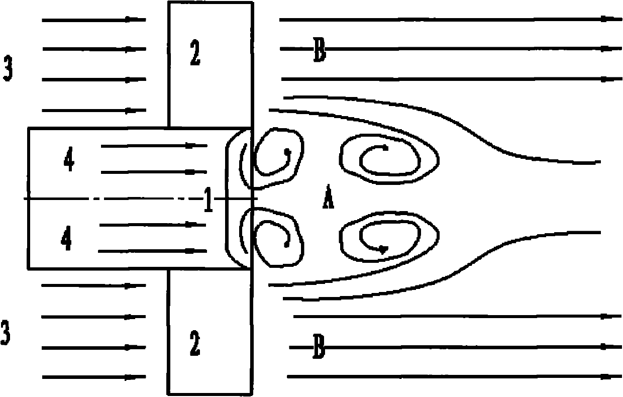
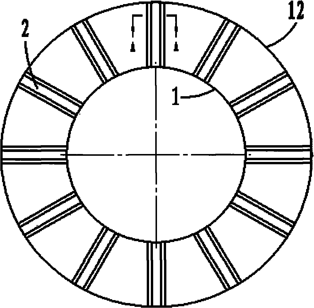
The invention provides a flame stabilizing device and method of an afterburner for a gas turbine engine. In the device, the original turbine rear frame supporting plate is replaced with the supporting plate with the cavities; and the device is characterized in that: the section of the supporting plate is in the shape of a wing with a suddenly expanded trailing edge and is provided with the cavities. The aim of stabilizing flame is fulfilled through a low-speed backflow region formed by flowing gas flow through the cavities of the supporting plate and the suddenly expanded part of the trailing edge. The invention provides the turbine rear frame supporting plate (2) of the afterburner for the gas turbine engine; the afterburner comprises a case (12), a turbine rear frame inner wall (1) and a plurality of turbine rear frame supporting plates (2), wherein the turbine rear frame supporting plates (2) are connected with the case (12) and the turbine rear frame inner wall (1); and the turbine rear frame supporting plate (2) is characterized by being provided with the cavities (9).
Description
technical field [0001] The invention relates to a flame stabilizing device for an afterburner in a gas turbine engine with afterburner, and more specifically relates to a scheme for improving the flame stabilization characteristics of the afterburner. Background technique [0002] The afterburner has been an important component of fighter jet engines since its invention. It adopts a direct-flow organization combustion scheme to greatly increase engine thrust in a short period of time. Traditional afterburners usually arrange V-shaped flame stabilizers in the flow field, and use high-speed airflow to bypass the recirculation zone formed by the blunt body structure to stabilize the flame and tissue combustion. However, the traditional blunt body stabilizer brings flow passage blockage and total pressure loss while stabilizing the flame, and its large structural size additionally increases the overall weight of the engine. Especially in the non-afterburning state, the addition...
Claims
Login to View More Application Information
Patent Timeline
 Patent Type & Authority Applications(China)
IPC IPC(8): F23R3/60F23R3/18
Inventor 金捷吴迪季鹤鸣刘雯佳杜刚柳阳刘玉英岳明王慧汝谭杰
Owner BEIHANG UNIV
Features
- Generate Ideas
- Intellectual Property
- Life Sciences
- Materials
- Tech Scout
- Unparalleled Data Quality
- Higher Quality Content
- 60% Fewer Hallucinations
Learn More Browse by: Latest US Patents, China's latest patents, Technical Efficacy Thesaurus, Application Domain, Technology Topic, Popular Technical Reports.
© 2025 PatSnap. All rights reserved.Legal|Privacy policy|Modern Slavery Act Transparency Statement|Sitemap|About US| Contact US: help@patsnap.com


