Supercharge Your Innovation With Domain-Expert AI Agents!

Reception apparatus

A technology of a receiving device and a receiving system, applied in the directions of synchronization device, broadcasting device, broadcasting system reception, etc., can solve the problems of insufficient accuracy, slow recovery, and inability to receive TMC data stably, and achieve the effect of high-efficiency radio processing

Active Publication Date: 2013-07-03
MITSUBISHI ELECTRIC CORP
View PDF1 Cites 0 Cited by
  • Summary
  • Abstract
  • Description
  • Claims
  • Application Information

AI Technical Summary

Problems solved by technology

[0006] However, in the conventional receiving apparatus, since the transmission time between TMC data is estimated, if the estimation accuracy of the transmission time is not enough, the TMC data may not be received stably.
In addition, if the receiver of the RDS data is unable to receive, even if the reception is temporarily cut off halfway, it is necessary to re-estimate the transmission time again, and there is a problem of slow recovery.

Method used


Image

  • Reception apparatus
  • Reception apparatus
  • Reception apparatus

Examples


Embodiment approach 1

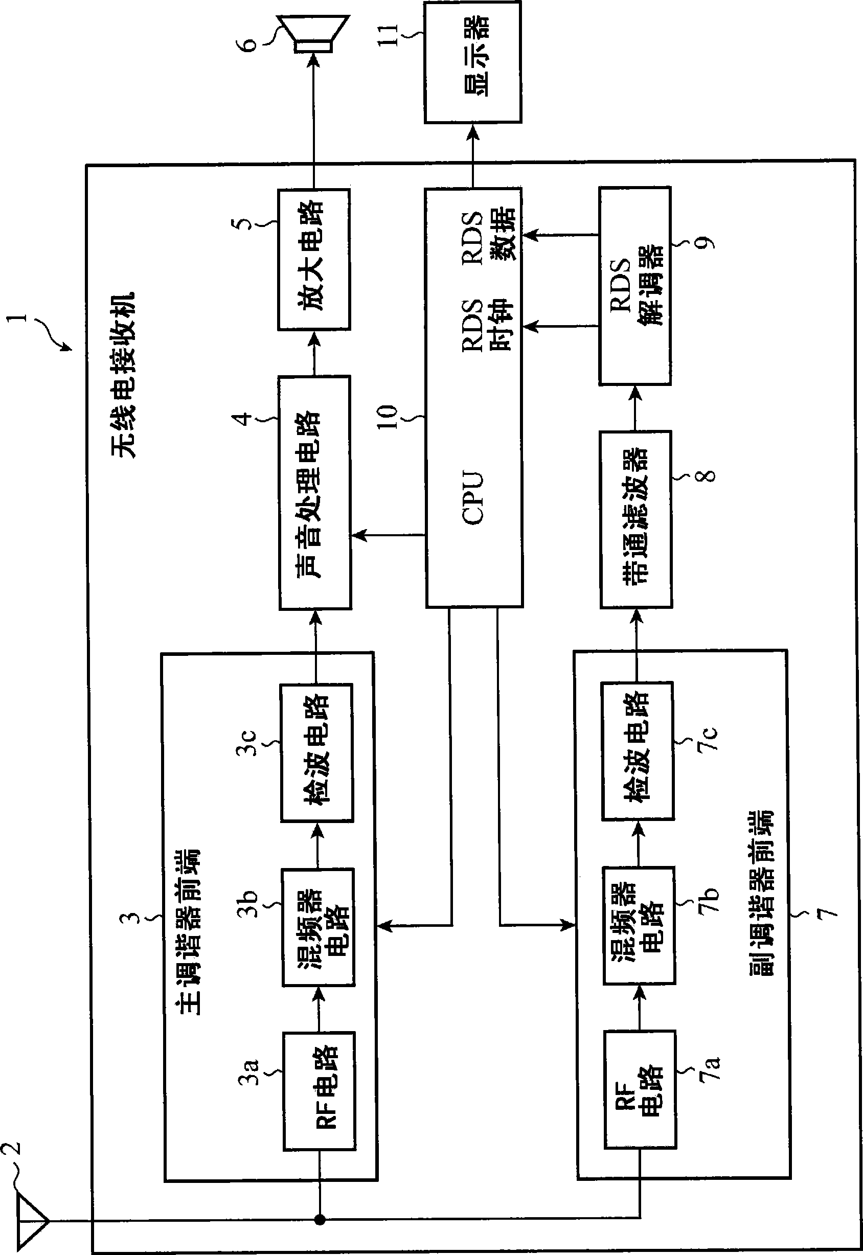
[0019] figure 1 It is a block diagram showing the configuration of a radio receiver to which the receiving device according to Embodiment 1 of the present invention is applied. exist figure 1 Among them, the radio receiver 1 of Embodiment 1 includes two tuners, a main tuner and a sub tuner, and includes a radio antenna 2, a main tuner front end 3, a sound processing circuit 4, an amplifier circuit 5, a speaker 6, and a sub tuner Front end 7 , bandpass filter 8 , RDS demodulator (RDS demodulator) 9 , CPU 10 , and display 11 .

[0020] A radio receiver 1 receives a plurality of broadcast waves through a radio antenna 2 , and these broadcast waves are detected by a main tuner front end 3 and supplied to an audio processing circuit 4 and an amplifying circuit 5 . The main tuner front end 3, the sound processing circuit 4, the amplifier circuit 5, and the elements related to the radio sound reproduction processing in the CPU 10 constitute a first receiving system for reproducing ...


PUM


Abstract

A receiving apparatus has counters 15 for counting intervals between group types 8A containing TMC data in RDS data in synchronization with an RDS clock signal, and causes a radio control unit 17 to control a sub tuner front end 7 so as to receive the group type 8A and to execute radio processing other than receiving the TMC data during counting of the counters.

Description

technical field [0001] The present invention relates to a vehicle-mounted receiving device, and more particularly to a receiving device for receiving traffic information (TMC; Traffic Message Channel: Traffic Message Channel) broadcast from an RDS (Radio Data System: Radio Data System) station. Background technique [0002] For example, in the conventional receiving device disclosed in Patent Document 1, the broadcast of a predetermined broadcast station selected by the viewer is received by the main tuner, and the broadcast by the RDS broadcast station is received by the background tuner (sub-tuner). Broadcast RDS data blocks (hereinafter referred to as packet types) are received. At this time, the transmission time between a specific packet type including TMC data and a different packet type is estimated, radio processing (task) such as searching for an alternative station is performed during this transmission time, and when the above-mentioned transmission time has elapse...

Claims


Application Information

Patent Timeline
Patent Type & Authority Patents(China)
IPC IPC(8): H04L7/00H04H20/55H04H40/27
CPCH04H20/42H04H2201/13H04H40/27H04H20/55
Inventor 中田和宏
Owner MITSUBISHI ELECTRIC CORP
Features
  • R&D
  • Intellectual Property
  • Life Sciences
  • Materials
  • Tech Scout
  • Unparalleled Data Quality
  • Higher Quality Content
  • 60% Fewer Hallucinations
Learn More