
Position detection device and method thereof

A detector and potential technology, applied in the input/output process of data processing, instruments, electrical digital data processing, etc., can solve the problems of increasing the wire density, reducing the signal of the lower electrode layer wire, and reducing the detection frequency, etc. , to achieve the effect of improving performance

Active Publication Date: 2011-04-20
EGALAX EMPIA TECH INC
View PDF5 Cites 12 Cited by
  • Summary
  • Abstract
  • Description
  • Claims
  • Application Information

AI Technical Summary

Benefits of technology

This patented technology allows users to easily locate specific areas within their handheld devices without having to manually input data like numbers. It uses multiple sensors with wide strip widths to cover large surface regions while still being able to accurately identify small presses. Additionally, this technology helps reduce interference between signals from neighboring buttons when they are adjacent. Users may use these techniques to control how many times they want them up (such as scrolling through documents).

Problems solved by technology

Technological Problem: Current solutions used for pressure -position recognition involve multiple sensors placed next to each other on top of another plate called a reference plane. These systems require precise timing synchronization among these sensor devices, making them difficult to use without errors caused during operation. Additionally, they often rely heavily upon expensive materials like gold powder to achieve accurate results despite being hit accidentally.

Method used

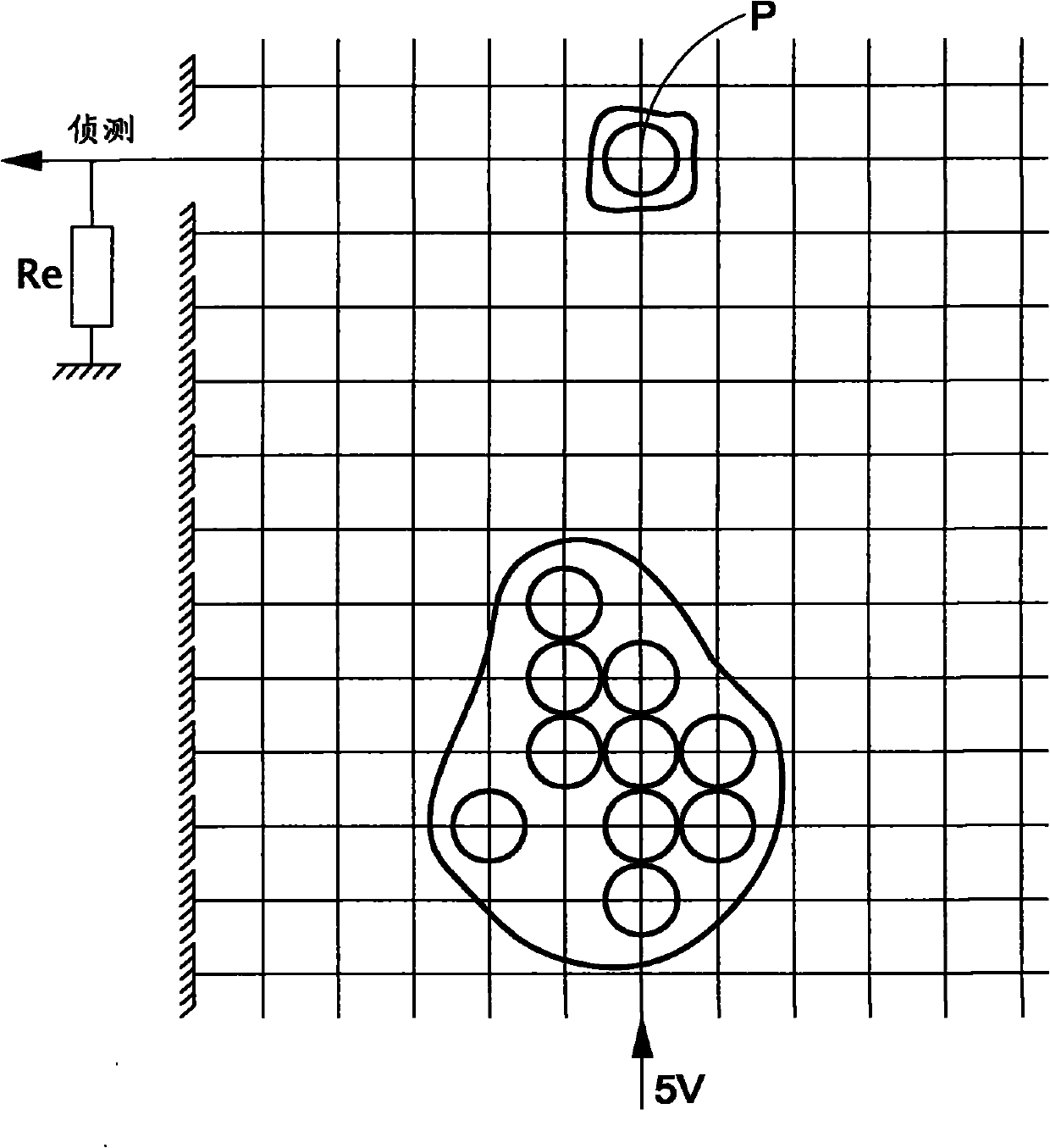

Image

  • Position detection device and method thereof
  • Position detection device and method thereof
  • Position detection device and method thereof

Examples


Embodiment Construction

[0100] In order to further explain the technical means and effects of the present invention to achieve the intended purpose of the invention, in conjunction with the accompanying drawings and preferred embodiments, the specific implementation, structure, Steps, features and effects thereof are described in detail below.

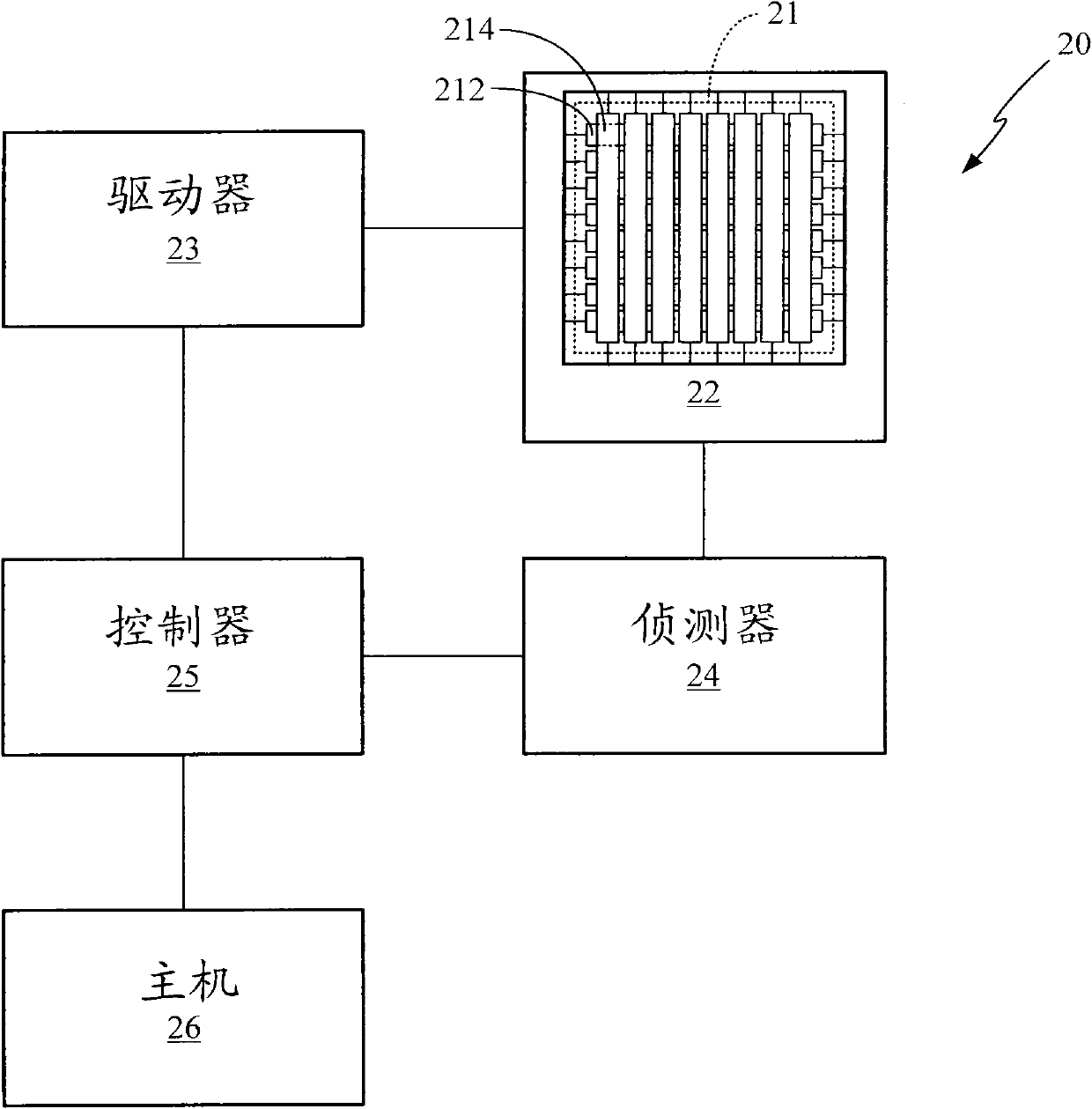
[0101] Please refer to Figure 2A As shown, the present invention provides a position detection device 20, including a sensor (Sensor) 21, a selector (SelectingDevice) 22, a driver (DrivingDevice) 23, a detector (Sensing) 24, a controller (ControllingDevice) 25 , Host (Host) 26.

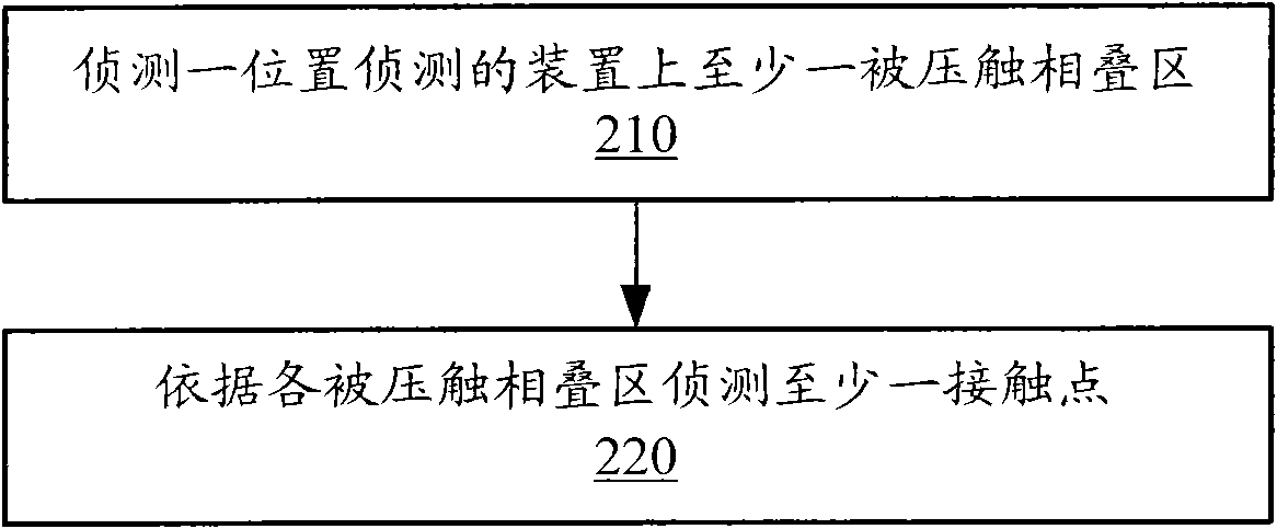
[0102] Refer again Figure 2B As shown, the present invention provides a method for multi-point position detection. First, as shown in step 210, at least one depressed intersecting region (depressed intersecting region) on a position detection device 20 is detected, and then as shown in step 220, at least one depressed intersecting region is detected according to each depressed i...


PUM


Abstract

The invention provides a position detection device and method thereof. A position detection device comprises a plurality of intersecting regions which consist of a plurality of conductive strips to form a plurality of intersecting regions, wherein a depressed intersecting region is formed when depressed conductive strips electrically contact with each other. The contact position and the total impedance can be determined based on the depressed intersecting region, wherein the total impedance is the shunt impedance of all the depressed intersecting regions.

Description


Claims


Application Information

Patent Timeline
Owner EGALAX EMPIA TECH INC
Learn More