Method and device for laying out distributive sites
A distributed and site-based technology, applied in the field of wireless communication, can solve the problems of distributed site definition dependence, antenna efficiency definition, etc., and achieve the effects of optimal distance, reduced transmission power, and reduced system power consumption
- Summary
- Abstract
- Description
- Claims
- Application Information
AI Technical Summary
Problems solved by technology
Method used
Image
Examples
Embodiment 1
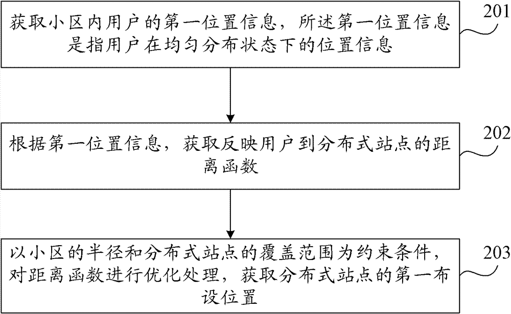
[0038] figure 2 It is a flow chart of the method for deploying distributed sites provided by Embodiment 1 of the present invention. Such as figure 2 As shown, the layout method of the distributed site of the present invention includes:
[0039] Step 201, acquiring first location information of users in the cell, where the first location information refers to location information of users in a state of uniform distribution;
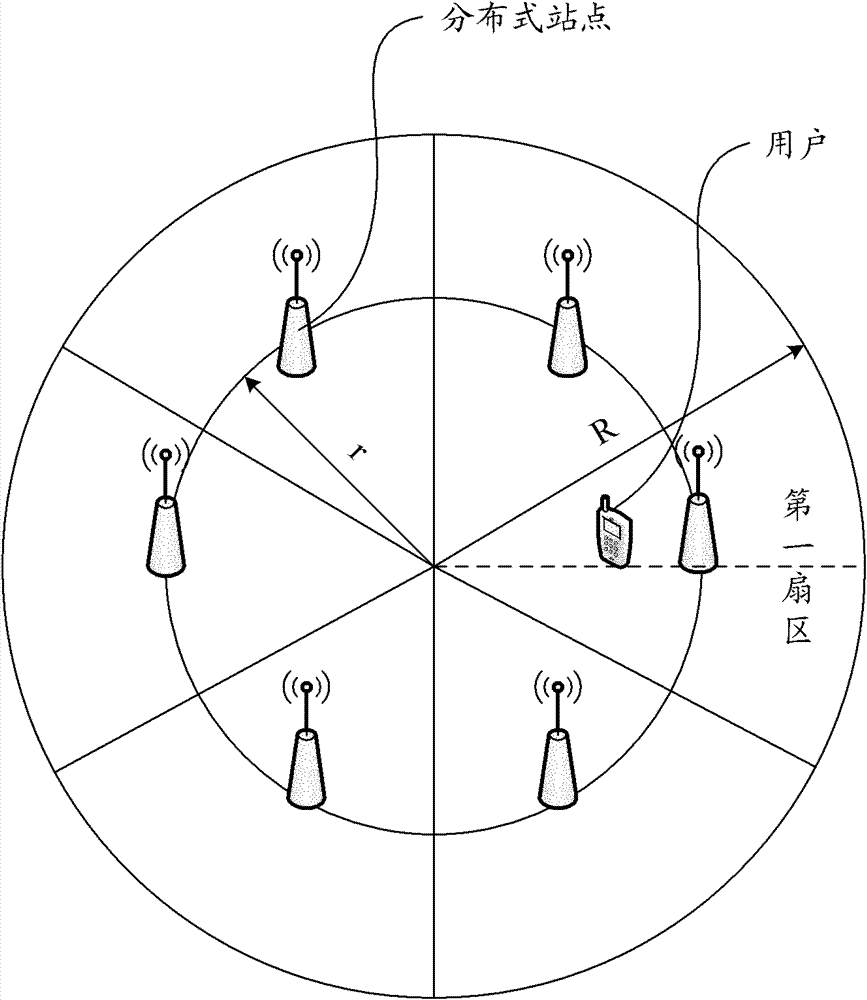
[0040] In this embodiment, it is assumed that the users are evenly distributed in the cell, and then the first location information of each user in the cell can be obtained according to the known radius of the cell, that is, the location of the user obtained under the condition of uniform distribution information. The location information includes the distribution probability of the users within the coverage of each distributed station and the location coordinates of the users.
[0041] Wherein, in this embodiment, it is assumed that N distributed si...
Embodiment 2
[0067] Figure 4 It is a flow chart of the method for deploying distributed sites provided by Embodiment 2 of the present invention. This embodiment is implemented based on Embodiment 1, and the difference is that, after obtaining the first deployment location of the distributed site, the method of this embodiment further includes:
[0068] Step 401, acquiring second location information of users in the cell, where the second location information refers to location information of users in a state of non-uniform distribution;
[0069] In this embodiment, the location information in the non-uniform distribution state refers to the location information of the user in the actual application environment. Specifically, in this embodiment, the second location information of each user may be acquired through the base station. Since each user's terminal will regularly report its location to the base station, the actual location information of the user can be obtained through the info...
Embodiment 3
[0091] Figure 5 It is a flow chart of the method for deploying distributed sites provided by Embodiment 3 of the present invention. This embodiment can be implemented based on Embodiment 1 or Embodiment 2. The difference is that, after obtaining the first deployment location of the distributed site, or after optimizing the first deployment location, the deployment method of this embodiment further includes: obtaining Steps for the number of optimally distributed sites. Wherein, the present embodiment is described on the basis of Embodiment 1, then as Figure 5 As shown, the layout method of this embodiment also includes:
[0092] Step 501 , with the goal of maximizing the energy efficiency of the system, the optimal number of distributed sites is obtained.
[0093] The step 501 is specifically to obtain the optimal number of distributed sites according to the formula (14);
[0094] N'=((α-1)w / P C ) 1 / α (14)
[0095] in, is a constant; P C is the pow...
PUM
 Abstract
Description
Claims
Application Information
 - R&D
- Intellectual Property
- Life Sciences
- Materials
- Tech Scout
- Unparalleled Data Quality
- Higher Quality Content
- 60% Fewer Hallucinations
Browse by: Latest US Patents, China's latest patents, Technical Efficacy Thesaurus, Application Domain, Technology Topic, Popular Technical Reports.
© 2025 PatSnap. All rights reserved.Legal|Privacy policy|Modern Slavery Act Transparency Statement|Sitemap|About US| Contact US: help@patsnap.com


