
Positioning and resetting structure of hand-operated direction valve

A manual reversing valve, reset structure technology, applied in the valve operation/release device, valve details, multi-way valve and other directions, can solve the problem of unable to spool, return to the original position, unable to automatically reset, etc., to achieve convenient operation , the effect of good operating feel

Active Publication Date: 2012-01-11
HEFEI CHANGYUAN HYDRAULICS
View PDF0 Cites 0 Cited by
  • Summary
  • Abstract
  • Description
  • Claims
  • Application Information

AI Technical Summary

Problems solved by technology

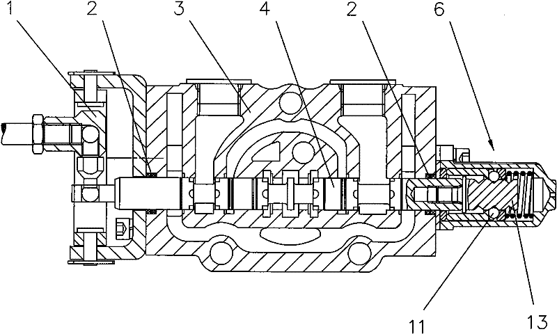
Figure 1a The manual reversing valve includes a manual reversing mechanism 1, a seal 2, a valve body 3, a valve core 4, and a spring return mechanism 5, and the spring return mechanism 5 includes a left spring seat 19, a right spring seat 20 and a return spring 10; In the reversing valve, after the manual reversing, the staff releases the manual reversing mechanism, and the valve core automatically returns to the original position under the action of the spring return mechanism, and there is a problem that the valve core cannot be positioned
Figure 1b The manual reversing valve includes a manual reversing mechanism 1, a seal 2, a valve body 3, a valve core 4, and a steel ball positioning mechanism 6, and the steel ball positioning mechanism 6 includes a positioning steel ball 11 and a positioning column 13; the reversing valve Among them, there are three annular grooves on the positioning column 13, and the reversing valve can be switched in three working gears. However, since the positioning steel ball is stuck in the annular groove during positioning, when the staff releases the manual reversing mechanism, The spring cannot make the spool return to the original position; the reversing valve can realize the positioning function of the spool in different working gears, but there is a problem that it cannot be automatically reset

Method used


Image

  • Positioning and resetting structure of hand-operated direction valve
  • Positioning and resetting structure of hand-operated direction valve
  • Positioning and resetting structure of hand-operated direction valve

Examples


Embodiment Construction

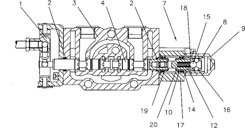
[0023] see figure 2 , image 3 , Figure 4 , Figure 5 , the positioning and reset structure of the manual reversing valve, the manual reversing valve includes a manual reversing mechanism 1, a valve body 3, a valve core 4, a rear end cover 17, a rear cover 9 and a positioning and resetting mechanism 7, and the left end of the valve core 4 is connected to There is a manual reversing mechanism 1, which is characterized in that the right end of the valve core 4 is set as a positioning reset mechanism 7; the positioning reset mechanism 7 is located in the cavity formed by the rear end cover 17 and the rear cover 9 arranged in sequence from left to right Inside; the positioning reset mechanism 7 includes back-moving spring 10, spring seat, positioning spring 12, pressure pad 14, positioning ball group and positioning sleeve 8; spring seat includes left spring seat 19 and right spring seat 20, left spring seat 19 and The right spring seat 20 is all sleeved on the spool 4 and ca...


PUM


Abstract

The invention discloses a positioning and resetting structure of a hand-operated direction valve comprising a hand-operated direction mechanism, a valve body, a valve core, a rear end cover, a rear cover and a positioning and resetting mechanism, wherein the positioning and resetting mechanism comprises a return spring, two spring seats, a positioning spring, a pressure pad, a positioning ball group and a positioning sleeve; the left spring seat and the right spring seat are both sheathed on the valve core and can axially slide along the peripheral surface of the valve core; the positioning spring and the positioning ball group are arranged in the cavity of the valve core; the positioning sleeve is arranged in the cavity formed by the rear cover and can slide in the cavity; and the inner peripheral surface of the positioning sleeve is provided with an annular step. The invention is especially suitable for the hand-operated direction valve and has the advantages that the direction valve has both positioning function and automatic resetting function and has convenient operation, good operation hand feel, low transformation cost, easy realization and the like.

Description

technical field [0001] The invention relates to a positioning and resetting structure, in particular to a positioning and resetting structure for a manual reversing valve. Background technique [0002] Manual reversing valve is a hydraulic component widely used in hydraulic systems, mainly used for switching medium flow direction. Manual reversing valves generally include the following components: manual reversing mechanism, seal, valve body, valve core, reset mechanism or positioning mechanism. The reset mechanism is used to make the spool return to the initial position after the reversing valve performs the reversing action. The positioning mechanism is used to fix the reversing valve in a certain working state or working position after the reversing valve performs the reversing action. In the prior art, the manual reversing valve is only provided with a spring return mechanism or only with a positioning mechanism. Figure 1a The manual reversing valve includes a manual ...

Claims


Application Information

Patent Timeline
Patent Type & Authority Patents(China)
IPC IPC(8): F16K11/02F16K31/44
Inventor 周洪涛陶新高张勇李洪芝
Owner HEFEI CHANGYUAN HYDRAULICS
Learn More