
Visual image display apparatus and method of using the apparatus to form a desired image

A technology of images, source images, used in projection devices, optics, instruments, etc.

Inactive Publication Date: 2013-08-28
费利克斯·R·拉雷塔
View PDF4 Cites 0 Cited by
  • Summary
  • Abstract
  • Description
  • Claims
  • Application Information

AI Technical Summary

Problems solved by technology

[0008] Furthermore, US Patent 4,475,126 does not disclose how to achieve an apparent 3D image with a seemingly continuous, seamless surface pattern

Method used


Image

  • Visual image display apparatus and method of using the apparatus to form a desired image
  • Visual image display apparatus and method of using the apparatus to form a desired image
  • Visual image display apparatus and method of using the apparatus to form a desired image

Examples


Embodiment Construction

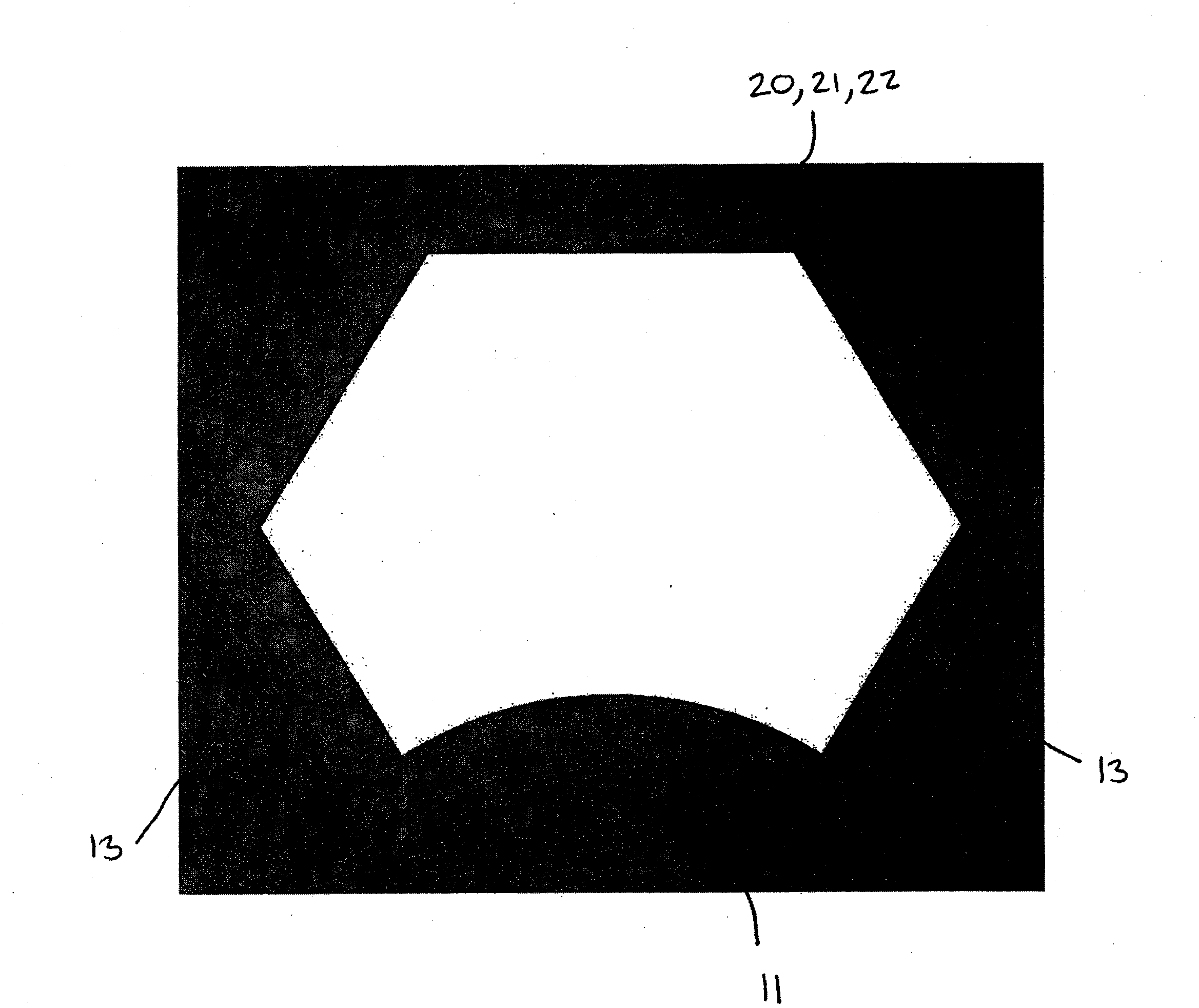
[0150] Referring now to the accompanying drawings, Figure 2 to Figure 5 Apparatus 3 is shown, generating a phantom of a three-dimensional kaleidoscope image according to an embodiment of the invention. The device 3 comprises a screen 4 having three plates 5a, 5b, 5c extending therefrom. The screen 4 shown in this embodiment is basically a triangle with three peripheral edges 6, 7, 8 and a predetermined curvature, which in image 3 with 4 is shown very clearly in , the reason for this will become clear later. An image is formed on the screen 4 , encompassing the entire front viewing surface 9 therein, and extending to the peripheral edges 6 , 7 , 8 of the screen 4 . Such an image is called a source image.

[0151] The screen 4 is formed from a transparent or translucent material so that an image projected onto it from its rear surface 10 can be seen on its front viewing surface 9 . The screen 4 is formed from a resilient material stretched over the frame into the desired ...


PUM


Abstract

An apparatus (3) for generating a three-dimensional kaleidoscopic image, comprising a screen (4) for the projection of images thereon, and a plurality of mirrors (31,32,33) surrounding the screen, wherein the screen is substantially shaped as a portion of a surface of a polyhedron or sphere with an icosahedral group symmetry of reflection, and the plurality of mirrors are aligned with planes extending through a projected centre of said polyhedron or sphere and intersecting each edge of the screen such that an image generated on the screen is reflected in the mirrors to produce an apparent three-dimensional image of said polyhedron or sphere.

Description

technical field [0001] The present invention relates to a device for displaying visual images, and more particularly to a device adapted to generate three-dimensional kaleidoscopic images, and a method of generating such images. Background technique [0002] A kaleidoscope is a well-known device that typically includes a tube formed of reflective flat surfaces constructed at 60-degree angles to each other. One end includes a viewing window for the user to view through the pipe, while the other end includes a cavity containing colored objects, the walls of which are transparent or translucent, allowing light to enter the pipe through the cavity. As the tube rotates, light bounces off the colored objects onto reflective planes on the tube's walls, creating repeating, symmetrical, attractive patterns. [0003] In the case of a tube kaleidoscope whose walls form a 60 degree angle to each other, the resulting pattern is a repeating hexagonal pattern where one sixth of a hexagon...

Claims


Application Information

Patent Timeline
Patent Type & Authority Patents(China)
IPC IPC(8): G02B27/08G02B27/22G06T19/00
CPCG02B27/08G02B27/2221G03B21/56G02B30/40
Inventor 费利克斯·R·拉雷塔
Owner 费利克斯·R·拉雷塔
Learn More