
Detachable drawer slide

A detachable drawer technology, applied to drawers, furniture parts, household appliances, etc., can solve the problems of easy sliding out of slide rails and damage, laborious operation, deformation and aging, etc., to prevent drawers from falling out of slide rails, use The effect of long life and easy operation

Inactive Publication Date: 2009-12-09
朱建华
View PDF1 Cites 18 Cited by
  • Summary
  • Abstract
  • Description
  • Claims
  • Application Information

AI Technical Summary

Problems solved by technology

[0004] However, in the above-mentioned disassembly process, the fingers need to be inserted into the guide groove of the inner rail, and the fingers are easily stained with oil; moreover, in order to ensure that the inner rail and the middle rail can be separated smoothly, the fingers need to pull the handle to make the two The angle between the two elastic strips becomes smaller, and eventually the elastic strip enters the chute of the fixed block. When pulling the handle, the fingers need to apply traction force along the longitudinal direction of the guide rail, which is laborious to operate. Two hands hold the drawer at the same time , but also let two fingers exert force on the handle at the same time. When the quality of the drawer is too heavy, it is not easy to achieve force balance, and it is easy to slip and even drop the drawer; in addition, the elastic strip of the patent buckle is made of plastic The material is prone to deformation and aging after a long time of use, the connection limit between the inner rail and the middle rail becomes unreliable, and the drawer is easy to slip out of the slide rail and break during use

Method used


Image

  • Detachable drawer slide
  • Detachable drawer slide
  • Detachable drawer slide

Examples


Embodiment Construction

[0030] The present invention will be further described in detail below in conjunction with the accompanying drawings and embodiments.

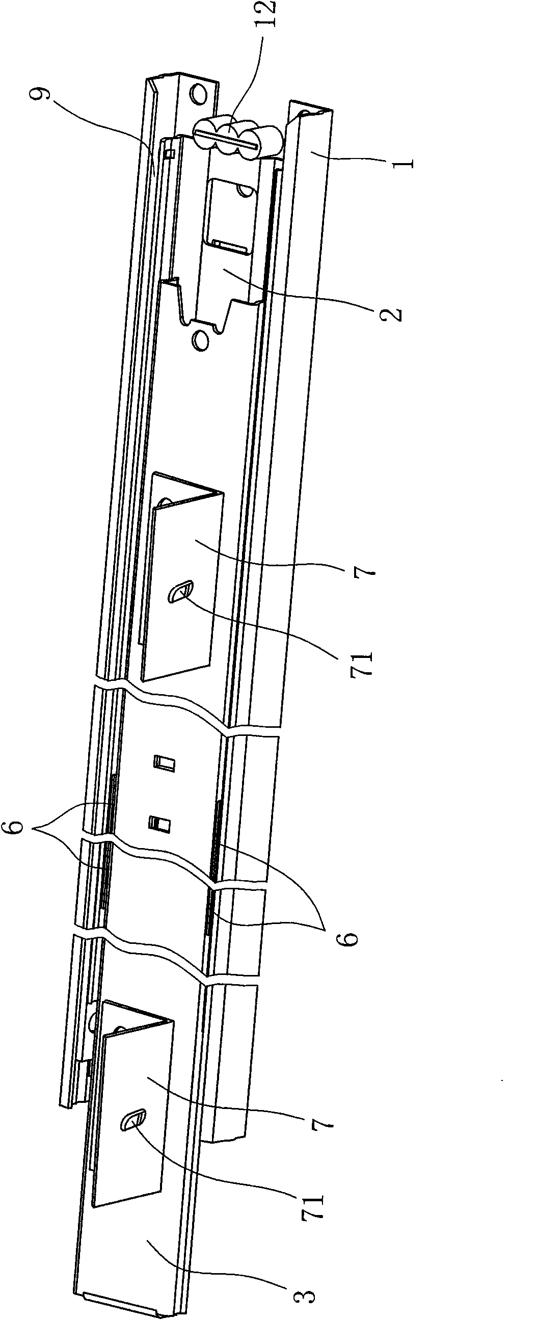
[0031] Such as Figure 1 to Figure 9 As shown, it is a schematic diagram of the structure of the drawer slide rail of the present invention, the drawer slide rail is a three-stage detachable slide rail, see figure 1 , including

[0032] A support seat 1 for connecting a cabinet frame for installing drawers, the support seat 1 has a web arranged longitudinally, and a side arm arranged along the longitudinal edge of the web plate of the support seat;

[0033] The outer slide rail 2 embedded between the two side arms of the support seat 1, the outer slide rail 2 also has a longitudinally arranged web and side arms arranged along the longitudinal edge of the outer slide rail 2 web, the outer slide rail 2. Relatively slide along the longitudinal direction of the support base and be limited to both ends of the support base; and

[0034] It can be...


PUM


Abstract

The invention provides a detachable drawer slide, comprising a supporting seat, an outer slide, an inner slide and a locking mechanism. The drawer slide is characterized in that the locking mechanism comprises a reed; wherein one end of the reed is a fixed end connected with a web plate of the inner slide, while the other end is an elastic movable end which is raised towards one side of the outer slide; the movable end is provided with a through hole; the outer slide is provided with a stop lug raising towards the reed on the web plate; the stop lug can be received in the through hole to prevent the inner slide from separating from the outer slide. Compared with the prior art, the drawer slide uses the reed instead of the prior elastic strip structure to ensure that the drawer can be separated from the slide only through lightly pressing the elastic movable end of the reed by the first finger, is in accordance with the characteristic of finger force application of a human body, and has the advantages of easy and convenient operation; and the finger need not put into the groove of the outer slide, and can not adhere to stains on the slide. The drawer slide is sanitary and clean for use, has uneasily deformed metal reed, long service life, and safer and more reliable limit.

Description

technical field [0001] The invention relates to a slide rail structure, in particular to a detachable drawer slide rail. Background technique [0002] At present, many drawers are fixed on cabinets or fixed frames through two-section or three-section sliding rails. This kind of drawer slide rail has a detachable function and a locking structure, which can prevent the drawer from being pulled out of the cabinet when it is pulled out. drop. [0003] Such as the Chinese utility model "three-fold detachable slide rail" whose patent number is ZL200720050407.0 discloses such a three-fold detachable slide rail structure, which includes an outer rail, a middle rail and an inner rail, and the three These parts are superimposed and nested together to form a stretchable slide rail device, in which the outer rail is used to connect with other objects, and the middle rail is used as an extension of the slide rail device, and the outer rail and the inner rail are connected through the mi...

Claims


Application Information

Patent Timeline
IPC IPC(8): A47B88/04A47B88/10A47B88/16A47B88/493
CPCA47B2088/0444A47B88/0422A47B88/427A47B2088/4235
Inventor 朱建华
Owner 朱建华
Learn More