
Component supplying device and surface mounter

A component supply and component technology, applied in the direction of electrical components, electrical components, etc., can solve the problems of unfavorable strip storage box compactness, component supply device transportation, etc.

Active Publication Date: 2012-05-30
YAMAHA MOTOR CO LTD
View PDF4 Cites 0 Cited by
  • Summary
  • Abstract
  • Description
  • Claims
  • Application Information

AI Technical Summary

Problems solved by technology

For this reason, it is ideal to increase the storage volume of the tape storage box, but if a tape storage box with a fixed size is used, it is not conducive to the compactness of the tape storage box or the transportation of the component supply device.

Method used


Image

  • Component supplying device and surface mounter
  • Component supplying device and surface mounter
  • Component supplying device and surface mounter

Examples


no. 1 approach

[0038] Next, a surface mounter according to a first embodiment of the present invention will be described with reference to the drawings.

[0039] 1. Overall structure

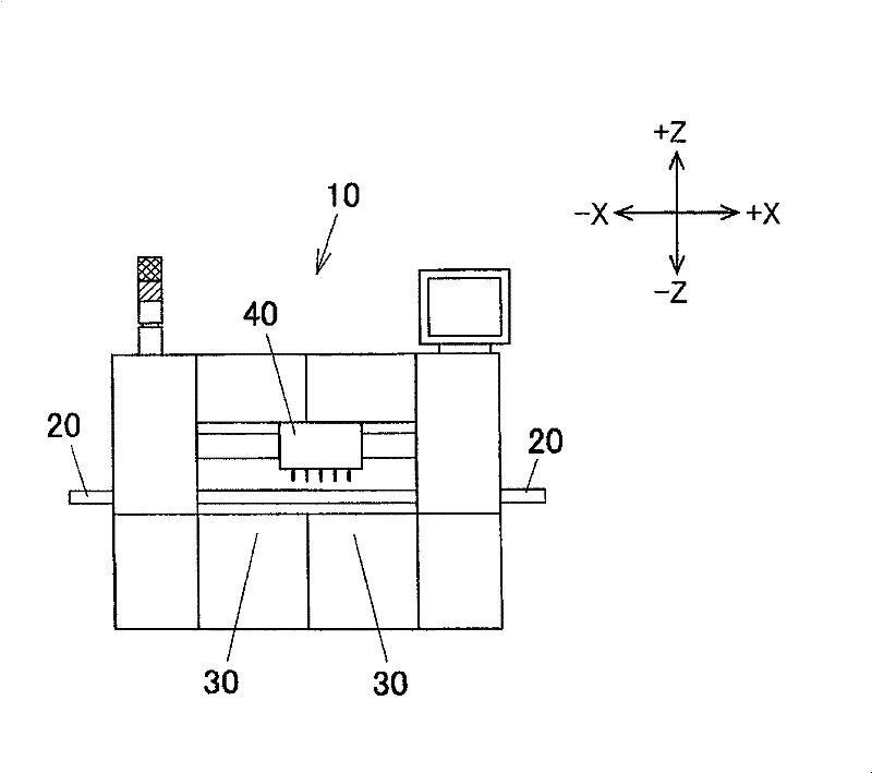
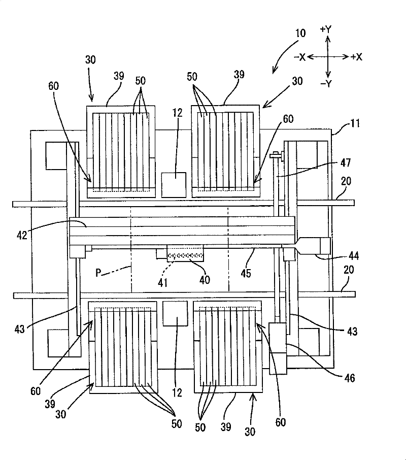
[0040] Such as figure 1 , figure 2 As shown, the surface mounter 10 includes; the conveyor belts 20, 20 arranged on the base 11 and used to transport the printed substrate P; the component supply parts 30 arranged on both sides of the conveyor belts 20, 20; above and used to install the head assembly 40 of electronic components.

[0041] The head assembly 40 is movable over an area between the component supply part 30 and the mounting position on the substrate P to take out electronic components from the component supply part 30 and mount them on the substrate P. As shown in FIG. Specifically, the head unit 40 is supported on a head unit support member 42 extending in the X-axis direction (the direction in which the conveyor belt 20 conveys the substrate) and can move along the X-axis direction. The head u...

no. 2 approach

[0091] Next, a second embodiment will be described. Figure 13 , Figure 14 It is a schematic diagram which shows the tape storage box used for the components supply apparatus of 2nd Embodiment. In the drawings, the same reference numerals are assigned to the same structures as those of the first embodiment, and detailed description thereof will be omitted. This also applies to other embodiments described later.

[0092] Such as Figure 13 , Figure 14 As shown, a retention mechanism 260 is provided within the strap storage box 200 . The holding mechanism 260 is used to hold (hold) the second case portion 220 at a predetermined position, and release the hold when a pressing force is applied to the second case portion 220 in a direction in which the storage volume expands. Specifically, the holding mechanism 260 is constituted by the metal plate 262 and the magnet 261. When the storage capacity of the cover tape CV in the tape storage box 200 is small, the second case part 2...

no. 3 approach

[0099] Next, a third embodiment will be described. Figure 15 shows the tape storage box used in the component supply device of the second embodiment, Figure 16 instantiated with Figure 15 Different strip containment boxes. In the third embodiment, the difference from the first embodiment is that the outer wall surface of the second case part 220 adopts a different structure from the first embodiment, and the rest of the structure is basically the same as the first embodiment. Wherein, in the tape storage box 200 of this embodiment, the shape, pattern, color and combination thereof of the outer wall surface of the second case part 220 are different from the outer wall surface of the first case part 210 so as to make it conspicuous. .

[0100] exist Figure 15 In the structure, the color of the outer wall surface of the second case part 220 is different from the color of the outer wall surface of the first case part 210, and in the state where the storage volume of the ta...


PUM


Abstract

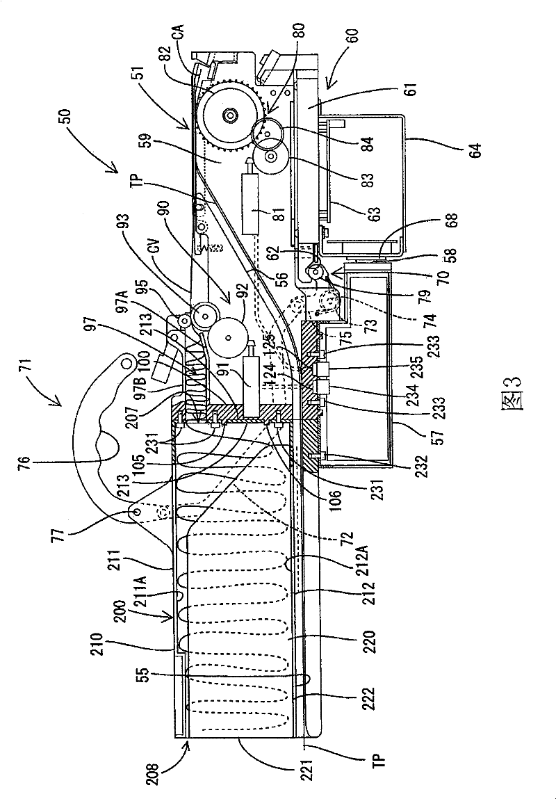
A parts feeding device constructed such that a tape receiving box of the device has a high degree of freedom in the size that can be set depending on use conditions. The parts feeding device (50) has A parts feeding device constructed such that a tape receiving box of the device has a high degree of freedom in the size that can be set depending on use conditions. The parts feeding device (50) hasa feeding device (80) for feeding a parts feeding tape TP toward a predetermined part take-out position, the parts feeding tape TP having a carrier tape CA and cover tape CV receiving parts at constana feeding device (80) for feeding a parts feeding tape TP toward a predetermined part take-out position, the parts feeding tape TP having a carrier tape CA and cover tape CV receiving parts at constant intervals, and also has a separation device (90) for separating the cover tape CV from the carrier tape CA by pulling the cover tape CV in a direction different from the feeding direction of the feet intervals, and also has a separation device (90) for separating the cover tape CV from the carrier tape CA by pulling the cover tape CV in a direction different from the feeding direction of the feeding device (80). Further, the parts feeding device (50) has a tape receiving box (200) for receiving the cover tape CV separated by the separation device (90). The receiving volume of the tape receivding device (80). Further, the parts feeding device (50) has a tape receiving box (200) for receiving the cover tape CV separated by the separation device (90). The receiving volume of the tape receiving box (200) is changeable.ing box (200) is changeable.

Description

technical field [0001] The present invention relates to a component supply device for supplying components such as IC with tape as a carrier, and a surface mounter equipped with the component supply device. Background technique [0002] Hitherto, a component supply device called a tape feeder has been known as one of mechanisms for supplying mounting components mounted on a surface mounting machine. A general component supply device feeds a component supply tape containing a plurality of components at regular intervals from a reel to a component take-out position. [0003] The component supply tape used in the component supply device generally includes a carrier tape for holding components and a cover tape for covering the carrier tape. For example, in the component supply device of Japanese Patent Document 1 (Japanese Patent Laid-Open Publication No. 2003-188584), while peeling the cover tape (cover tape) from the carrier tape, the carrier tape after this peeling is sent t...

Claims


Application Information

Patent Timeline
Patent Type & Authority Patents(China)
IPC IPC(8): H05K13/02
Inventor 米光正典大贯友和塚越和宏
Owner YAMAHA MOTOR CO LTD
Learn More