Cylinder manifold contact switching-on device for compensating cylinder manifold thickness

A technology of busbars and stop devices, applied in the direction of busbar/circuit layout, etc.

Active Publication Date: 2009-08-19
SIEMENS AG
View PDF3 Cites 2 Cited by
  • Summary
  • Abstract
  • Description
  • Claims
  • Application Information

AI Technical Summary

Problems solved by technology

The disadvantage of this embodiment is that the contact pins are present as parts before they are assembled on the fixing part

Method used


Image

  • Cylinder manifold contact switching-on device for compensating cylinder manifold thickness
  • Cylinder manifold contact switching-on device for compensating cylinder manifold thickness
  • Cylinder manifold contact switching-on device for compensating cylinder manifold thickness

Examples


Embodiment Construction

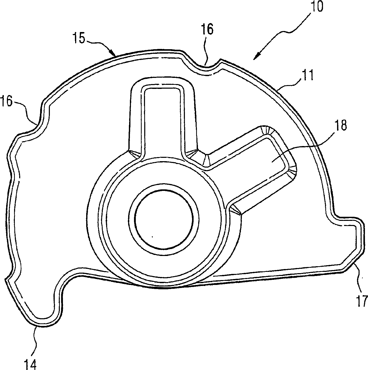
[0075] figure 1 A distance block 10 according to an embodiment is shown. The spacer 10 has a raised overall support edge 15 . The raised overall support edge 15 is interrupted by grooves 16 so that individual convex edges 11 are formed. Bosses 14 , 17 are located at the respective ends of the raised overall support leg 15 . For reinforcement, the spacer 10 has reinforcing ribs 18 which extend substantially radially from the center to the outside. The illustrated distance block 10 is circular segment-shaped. Of course, other embodiments are also possible for the spacer 10 , in which the spacer has an eccentrically convex overall support edge 15 or also a parabolic or exponentially shaped overall support edge 15 .

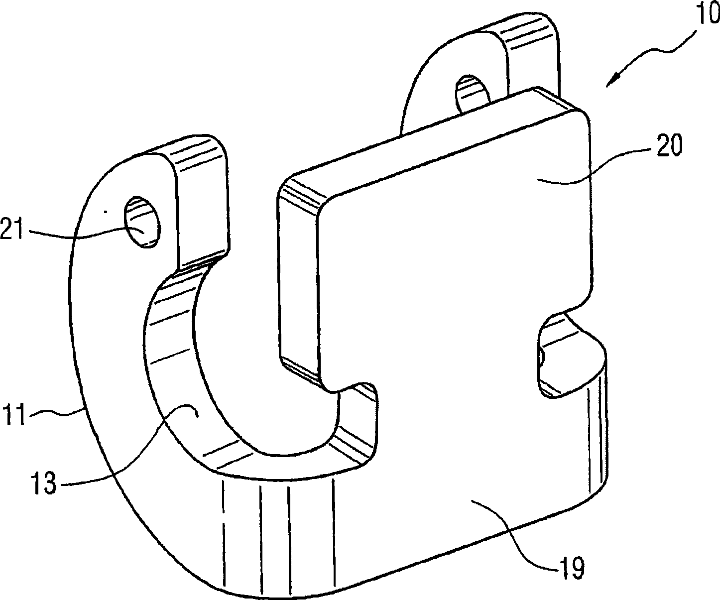
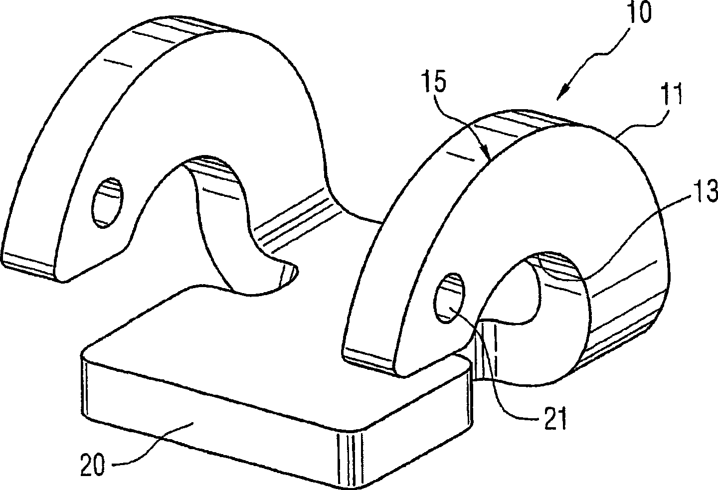
[0076] figure 2 and image 3 A distance block 10 according to another embodiment is shown. Such a spacer 10 has two convex sides 11 each arranged in a plane. Here, the planes in which the convex support edge 11 lies are parallel to one another. The two conv...


PUM


Abstract

The invention relates to a spacer (10) for matching a gap in a spring hook (30) to the thickness of a conductor bar (50), which spacer can be fitted on the spring hook (30) in such a way that it is capable of rotating about an axis of rotation (60) and has, in order to bear against a conductor bar (50), at least one convexly shaped region (11), wherein the axis of rotation (60) is located on the side of the opening of the convex region (11) behind said convex region (11); and furthermore a spring hook (30) with a hook limb (31) on the device side which is fixed to the device (70) and at least one clamping hook limb (32), which is designed to be substantially parallel to the device-side hook limb (31), for absorbing a clamping force and at least one connecting web (33), which connects the two hook limbs (31, 32), and with a device (34) for the rotatable arrangement of a spacer (10), wherein the axis of rotation (60) of the device (34) for the rotatable fixing of the spacer (10) is arranged on the clamping hook limb (32).

Description

technical field [0001] The invention relates to a busbar contacting device with busbar thickness compensation, which is used for fixing or hanging on the busbar and electrically contacting an electrical device. [0002] One of the technical subjects of the present invention is a spacer for matching the spacing in the snap hook to the thickness of the bus bar, which is rotatably mounted on the snap hook around the axis, and in order to be supported on the bus bar Instead, there is at least one convex region. Another technical subject of the present invention is a snap hook for hanging electrical equipment on a busbar, comprising at least one hook arm fixed to the equipment on the equipment side, and comprising at least one hook designed to be substantially parallel to the equipment side The clamping hook arm of the arm is used to bear the clamping force, and includes a connecting plate connecting the two hook arms, and includes a device for rotatably mounting a distance block....

Claims


Application Information

Patent Timeline
Patent Type & Authority Applications(China)
IPC IPC(8): H02B1/21
CPCH02B1/21
Inventor 格哈德·布莱默拉尔夫-埃伯哈德·布鲁希克乔尔格·休斯曼诺伯特·玛希克罗伯特·普罗茨斯蒂芬·斯库德罗艾尔弗雷德·斯汤拉尔夫-埃伯哈德·布鲁希克
Owner SIEMENS AG
Why Eureka
Try Eureka