
Running-in usage of elevator and alley way fixed equipment in destination logging group elevator system

A technology of elevator system and destination, which is applied in the field of installation of fixed equipment in elevator corridor and network registration, which can solve problems such as time-consuming

Active Publication Date: 2009-05-27
OTIS ELEVATOR CO
View PDF0 Cites 3 Cited by
  • Summary
  • Abstract
  • Description
  • Claims
  • Application Information

AI Technical Summary

Problems solved by technology

This is an elaborate, time-consuming commissioning process, especially in large buildings with numerous destination entry devices

Method used


Image

  • Running-in usage of elevator and alley way fixed equipment in destination logging group elevator system
  • Running-in usage of elevator and alley way fixed equipment in destination logging group elevator system
  • Running-in usage of elevator and alley way fixed equipment in destination logging group elevator system

Examples


Embodiment Construction

[0013] figure 1 is a perspective view of a destination entry elevator system 10 within a building 12 . The building 12 includes 5 floors, including a lobby floor L, a second floor F2, a third floor F3, a fourth floor F4, and a fifth floor F5. Group elevator system 10 includes three elevators 14 a , 14 b , and 14 c each operable to transport passengers to any floor of building 12 . Although 3 elevators 14a-14c and 5 floors L and F2-F5 are shown, it will be appreciated that the present invention is for use with a destination group elevator system having any number of elevators to serve any number of floors.

[0014] The operation of each elevator is controlled by a dedicated elevator car controller. In particular, elevator 14a is controlled by cab controller 16a, elevator 14b is controlled by cab controller 16b, and elevator 14c is controlled by cab controller 16c. The elevator car controllers 16a - 16c are interconnected and in communication via a communication loop 18 .

...


PUM


Abstract

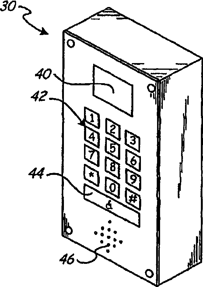
A destination entry input device (30, 35) is commissioned in a group elevator system (10). The destination entry input device (30, 35) is connected to a dispatch controller (20). A network address is input into the destination entry input device (30, 35) corresponding to an installation location of the destination entry input device (30, 35). When the network address is input, installation location information related to the installation location of the destination entry input device is downloaded to the destination entry input device (30, 35) and verified.

Description

technical field [0001] The invention relates to the field of elevator control, and more particularly relates to the installation and network registration of the fixed equipment of the elevator corridor in the elevator system of the destination landing group. Background technique [0002] Traditional group elevator systems include hall call modules near the elevators on each floor. Typically, the elevator call module includes up and down buttons that are pressed by passengers when elevator service is required. Each elevator call module is assigned a network address that the elevator controller uses to associate the hallway call module with its floor location. When one of the buttons on the hall call module is pressed, the elevator controller assigns the elevator that will most efficiently deliver passengers in the desired direction. The elevator controller determines which floor to send the elevator to based on the network address of the hall call module on which the button...

Claims


Application Information

Patent Timeline
Patent Type & Authority Applications(China)
IPC IPC(8): G08C19/16
CPCB66B2201/463B66B2201/4615B66B1/468G08C19/16B66B1/18G08C19/00B66B1/46
Inventor M·P·弗林P·A·斯特拉尼里W·蒙塔格R·曼吉尼
Owner OTIS ELEVATOR CO
Learn More