Intake manifold for an internal combustion engine provided with metallic reinforcement brackets for fastening the fuel common rail
A technology of intake manifold and internal combustion engine, applied in combustion air/combustion-air treatment, fuel injection device, charging system, etc., can solve the problems of increased manufacturing cost, assembly cost, load loss, etc.
- Summary
- Abstract
- Description
- Claims
- Application Information
AI Technical Summary
Problems solved by technology
Method used
Image
Examples
Embodiment Construction
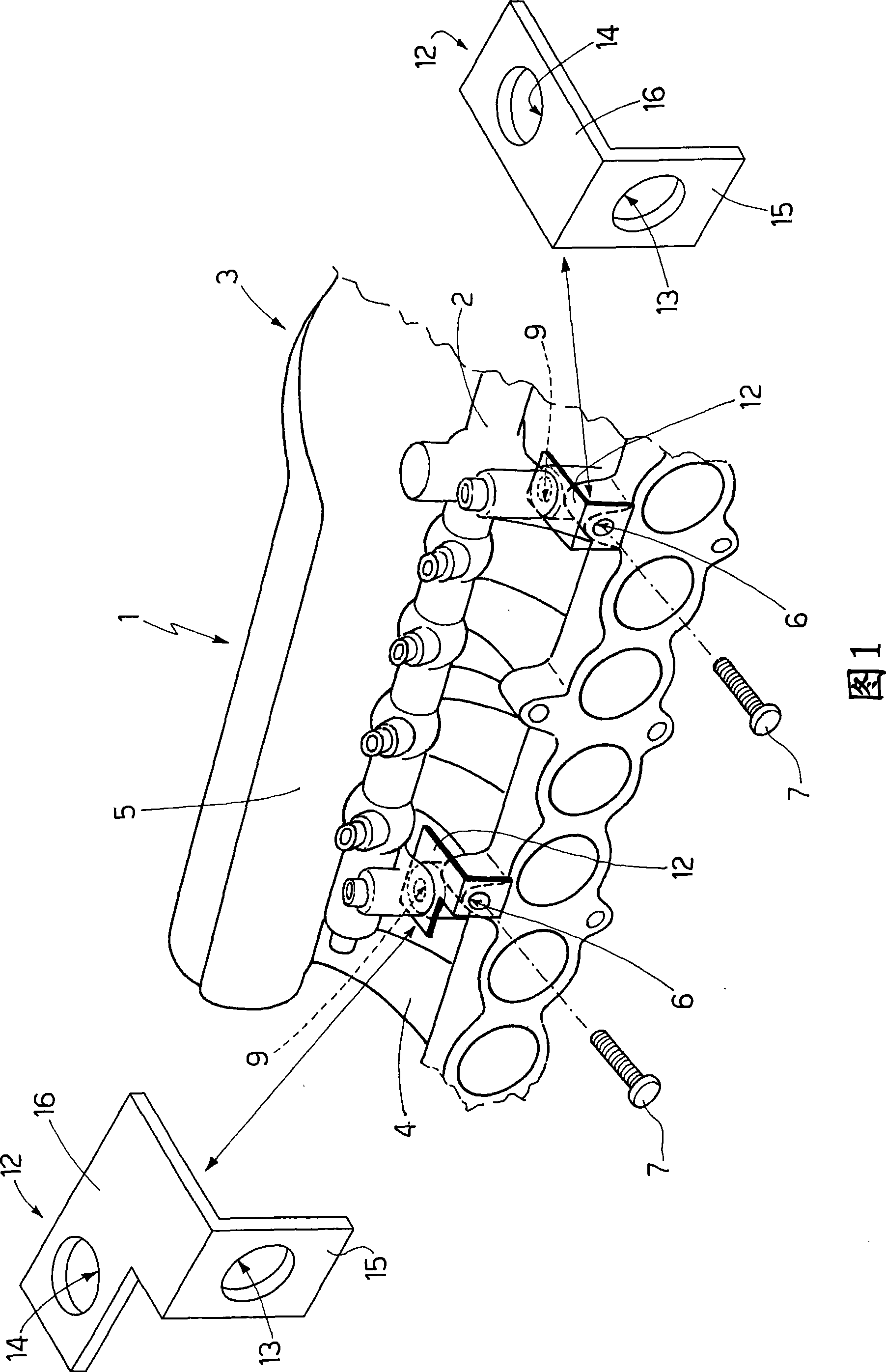
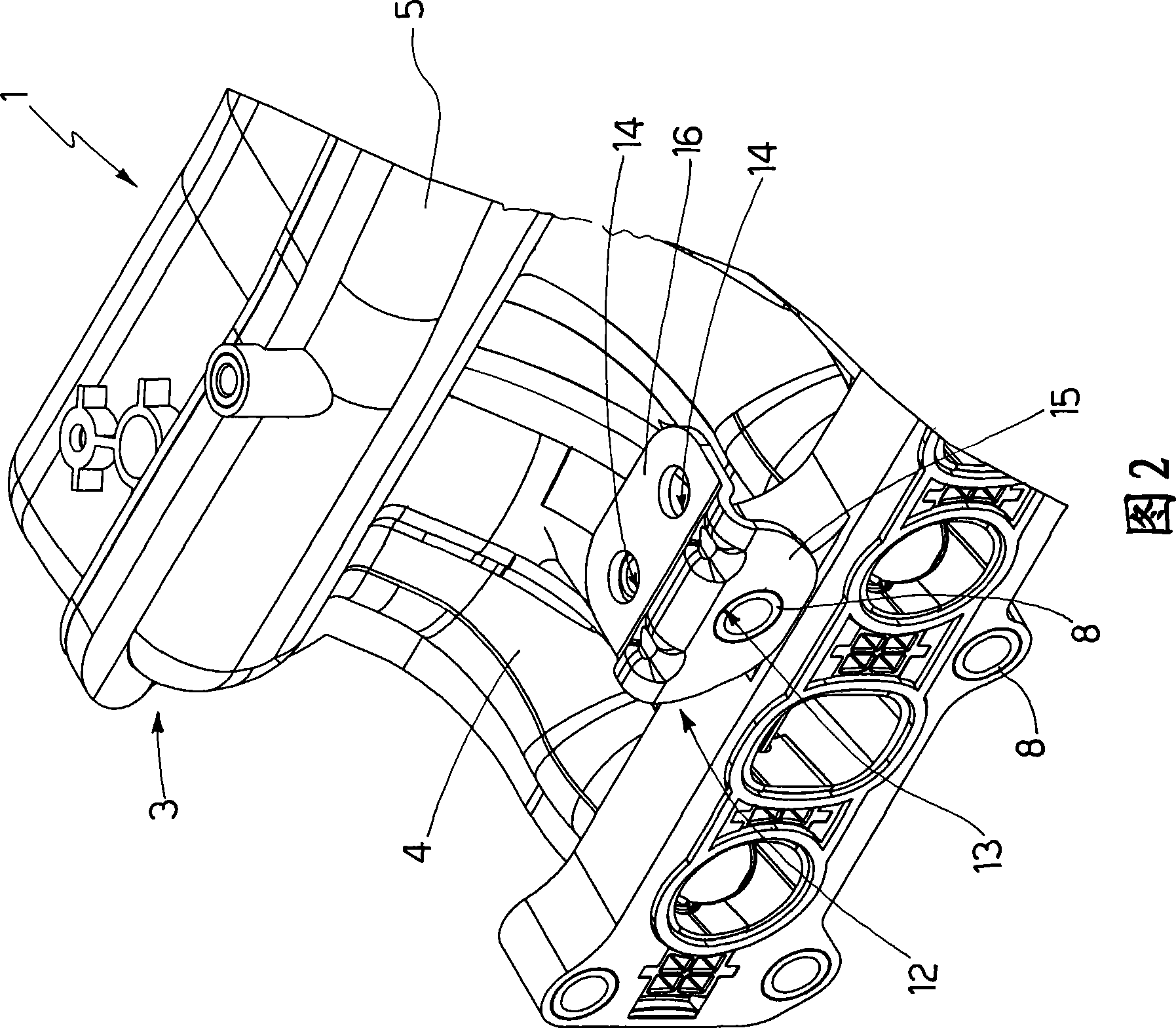
[0016] In FIG. 1 , reference numeral 1 generally designates an internal combustion engine comprising an engine cover in which several cylinders (not shown) are located and a common rail 2 receiving pressurized fuel and connected to several injectors (not shown), Each injector injects fuel into a corresponding cylinder.
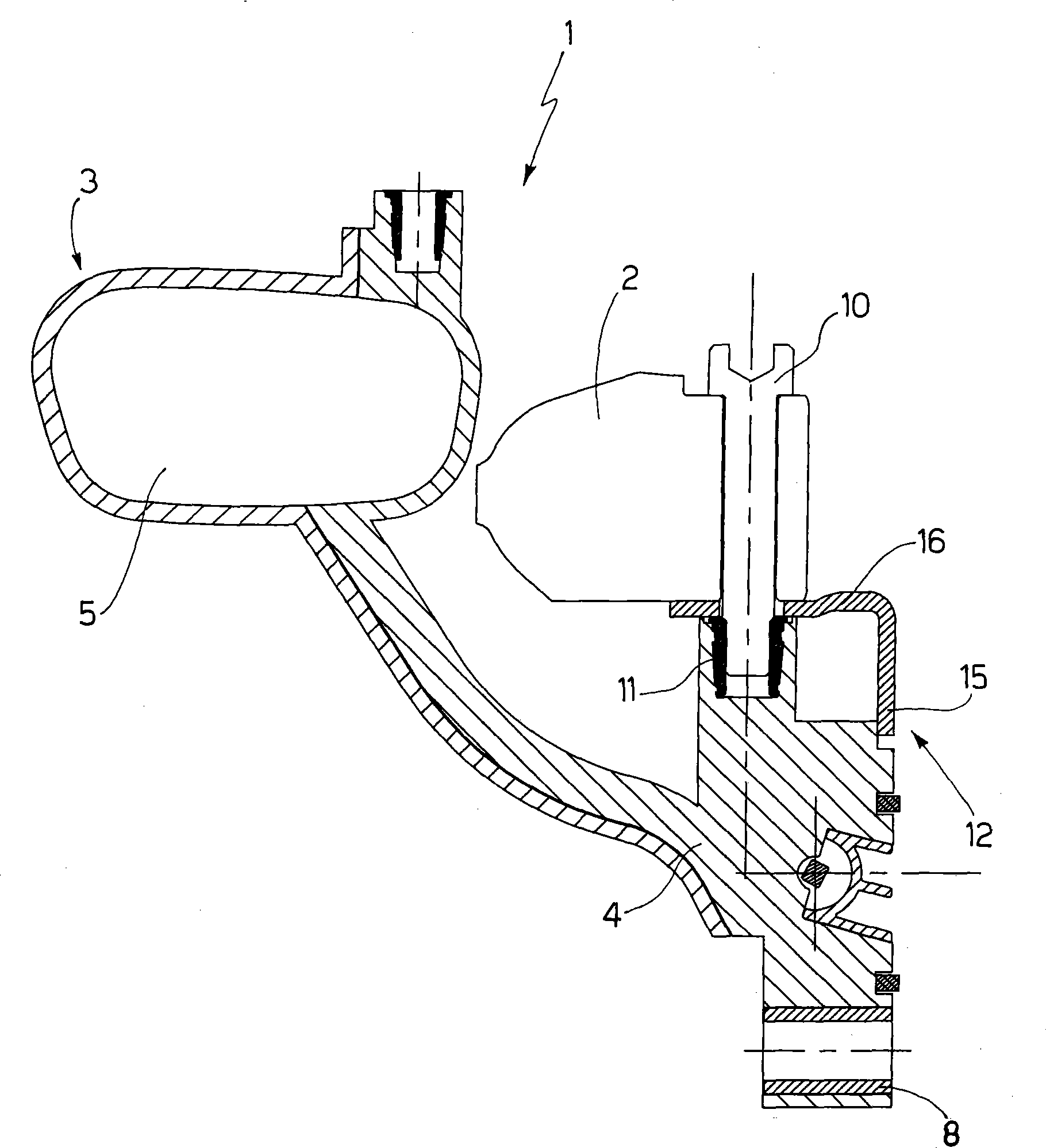
[0017] The internal combustion engine 1 further comprises a common intake manifold 3 which in turn comprises a central body 4 and ducts. In the central body 4 there is provided an intake chamber 5 receiving the intake air, while ducts are adapted to connect the intake chamber 5 to corresponding cylinders of the internal combustion engine 1 .
[0018] The intake manifold 3 comprises a first through hole 6, which is provided in the central body 4 of the intake manifold 3, allowing to fasten the intake manifold 3 itself to the Engine cover. Corresponding metal bushings 8 are embedded in each first assembly hole 13 .
[0019] Such as image 3 As shown, the inta...
PUM
 Abstract
Description
Claims
Application Information
 - R&D
- Intellectual Property
- Life Sciences
- Materials
- Tech Scout
- Unparalleled Data Quality
- Higher Quality Content
- 60% Fewer Hallucinations
Browse by: Latest US Patents, China's latest patents, Technical Efficacy Thesaurus, Application Domain, Technology Topic, Popular Technical Reports.
© 2025 PatSnap. All rights reserved.Legal|Privacy policy|Modern Slavery Act Transparency Statement|Sitemap|About US| Contact US: help@patsnap.com


