
Inclined pin structure

A technology of oblique pin and oblique pin rod, which is applied in the field of oblique pin structure

Inactive Publication Date: 2009-01-21
MITAC PRECISION TECH(KUNSHAN) CORP
View PDF0 Cites 5 Cited by
  • Summary
  • Abstract
  • Description
  • Claims
  • Application Information

AI Technical Summary

Problems solved by technology

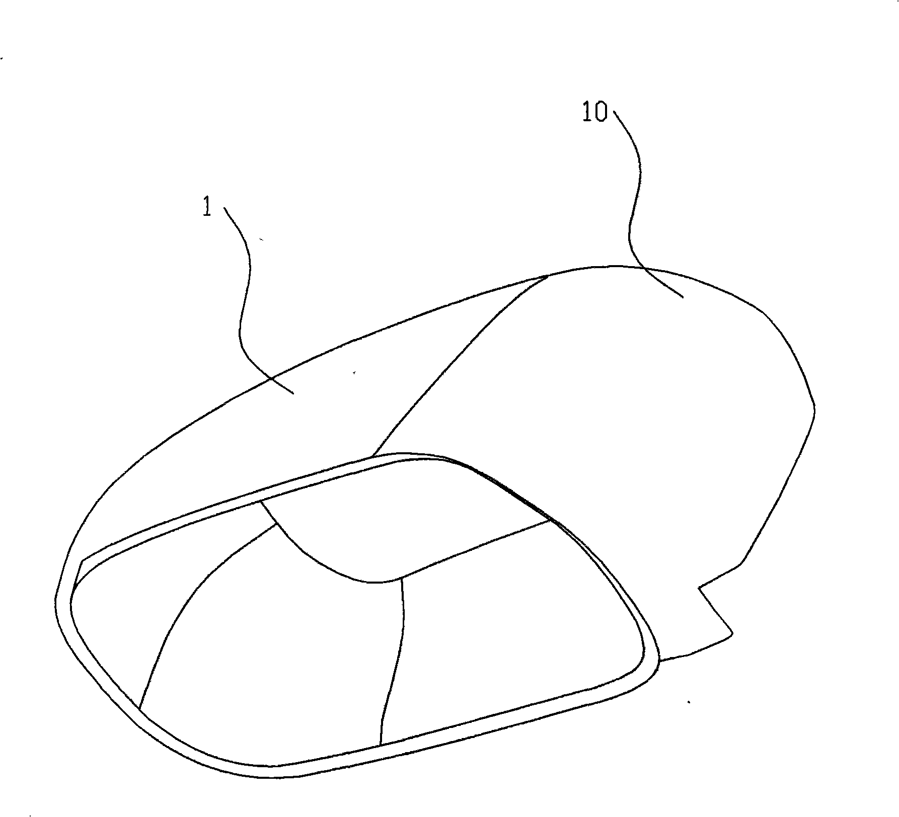
If this product 1 is to be manufactured, it is difficult to complete the above-mentioned simple oblique pin form.

Method used


Image

  • Inclined pin structure
  • Inclined pin structure
  • Inclined pin structure

Examples


Embodiment Construction

[0018] read on figure 2 , which is a three-dimensional schematic diagram of a product with a large area of ​​barbs. Due to the large area of ​​barbs 10 present in this product 1 . If this product 1 will be manufactured, it will be difficult to complete by adopting the current simple oblique pin molding. And a preferred embodiment of the present invention can solve the molding of this product.

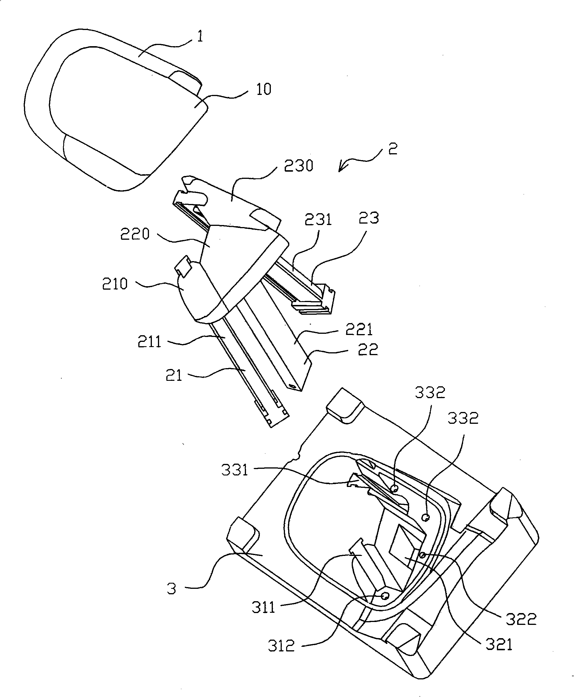
[0019] Please refer to image 3 , Figure 4 , which are respectively shown as a three-dimensional exploded view of the oblique pin structure of a preferred embodiment of the present invention and its corresponding products, and a three-dimensional exploded view of the oblique pin group of the oblique pin structure of a preferred embodiment of the present invention.

[0020] As shown in the figure, the oblique pin structure of the present invention is applied to the molding of a product 1 with a large-area barb 10 inside. In this preferred embodiment, the oblique pin structure inclu...


PUM


Abstract

The invention relates to an inclined pin structure which is used for shaping products with a large area of barbs inside. The inclined pin structure comprises a core that is provided with a plurality of inclined pin holes; an inclined pin group that comprises one or a plurality of inclined pins one-to-one corresponding to the inclined pin holes, and each inclined pin comprises an inclined pin lever and an inclined pin insert that is inserted and fixed near to the top of the inclined pin lever and is movably arranged in the corresponding inclined pin hole by the respective inclined pin lever. Excellently, the bottom of one or a plurality of inclined pin inserts is provided with one or a plurality of positioning parts respectively, and the core is provided with one or a plurality of positioning holes correspondingly. By adopting the inclined pin structure and the inclined pin insert that is inserted and fixed on the inclined pin lever, and a corresponding shape for barb shaping of products is formed by the inclined pin group formed by piecing together the inclined pins, thus achieving the purpose of shaping the products with a large area of barbs inside easily.

Description

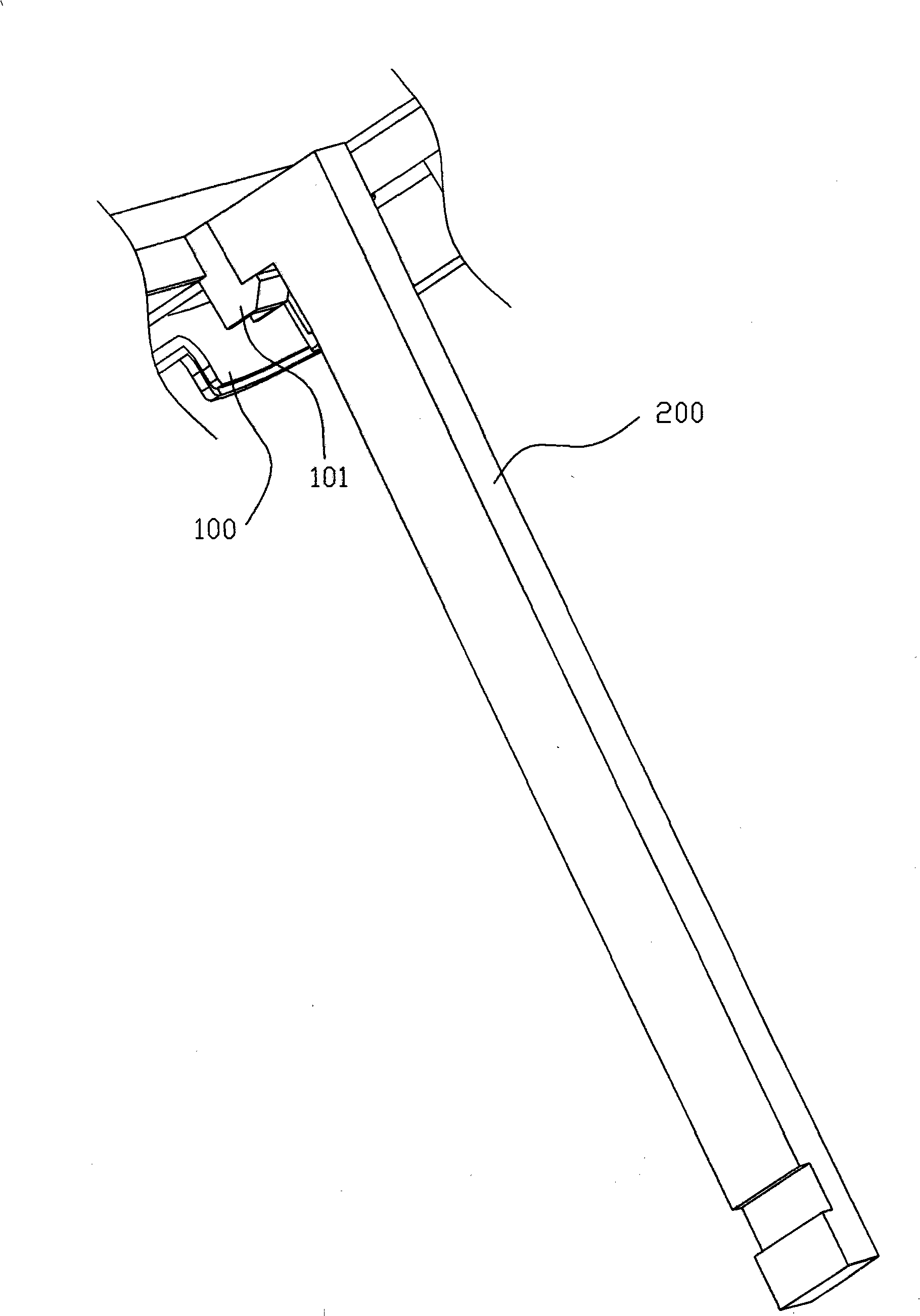
【Technical field】 [0001] The invention relates to a slanted pin structure, in particular to a slanted pin structure with large-area barbs inside a product. 【Background technique】 [0002] When producing plastic products, it is often encountered that there are undercuts on the product. see figure 1 , which is a three-dimensional schematic view of the oblique pin structure in the prior art. As shown in the figure, for the situation that there are barbs 101 on the product 100, if the oblique pin structure is not used, the barbs 101 cannot be separated from the mold core (not shown) when the mold is opened, so it cannot be completely formed by the mold core (not shown in the figure). shown) forming. Since the barb 101 has a simple structure and a small area, the above-mentioned problem is solved by adopting a simple one-piece oblique pin 200 to form the barb 101 accordingly. After the mold is opened, the moving direction of the product 100 is consistent with the mold opening...

Claims


Application Information

Patent Timeline
IPC IPC(8): B29C33/44B29C45/33
Inventor 雷雪宁
Owner MITAC PRECISION TECH(KUNSHAN) CORP
Learn More