
Automatic glue dropping system with synchronous material feed and method thereof

A technology for automatic dispensing and dispensing, which is applied to devices and coatings that apply liquid to the surface, which can solve the problems of expensive mechanical arm devices, increase manufacturing costs, and consume operating time, so as to increase manufacturing costs and reduce processing. time, the effect of speeding up the process

Inactive Publication Date: 2009-01-14
KROMAX INT CORP
View PDF0 Cites 12 Cited by
  • Summary
  • Abstract
  • Description
  • Claims
  • Application Information

AI Technical Summary

Benefits of technology

This new type of apparatus has two main technical benefits - one being added on top of existing systems like robots (which require more space) while another adding functionality within them such as carrying loads between different locations instead of just moving along rails. These improvements make these machines faster and easier to use compared with older designs without requiring extra components.

Problems solved by technology

This patented technical problem addressed in this patents relates to improving automated dispenser systems' performance and reducing their size while maintaining consistently accurate results over longer periods without requiring constant maintenance.

Method used


Image

  • Automatic glue dropping system with synchronous material feed and method thereof
  • Automatic glue dropping system with synchronous material feed and method thereof
  • Automatic glue dropping system with synchronous material feed and method thereof

Examples


Embodiment Construction

[0056] For a more complete understanding of the present invention and its advantages, detailed description will be given below with reference to the accompanying drawings, wherein like numerals represent like components. It should be understood that all the specific embodiments in the present invention are for illustrative purposes only, so except for the specific embodiments herein, the present invention can also be widely applied in other embodiments, and the present invention is not limited to any implementation For example, the scope of the appended claims and their equivalents should be determined.

[0057] Throughout this patent specification, "a specific embodiment" means to describe a specific feature, structure or characteristic related to a specific embodiment, and in the present invention, the number of the specific embodiment is at least one. Therefore, the appearance of "in a specific embodiment" in this specification does not necessarily mean that the same embodi...


PUM


Abstract

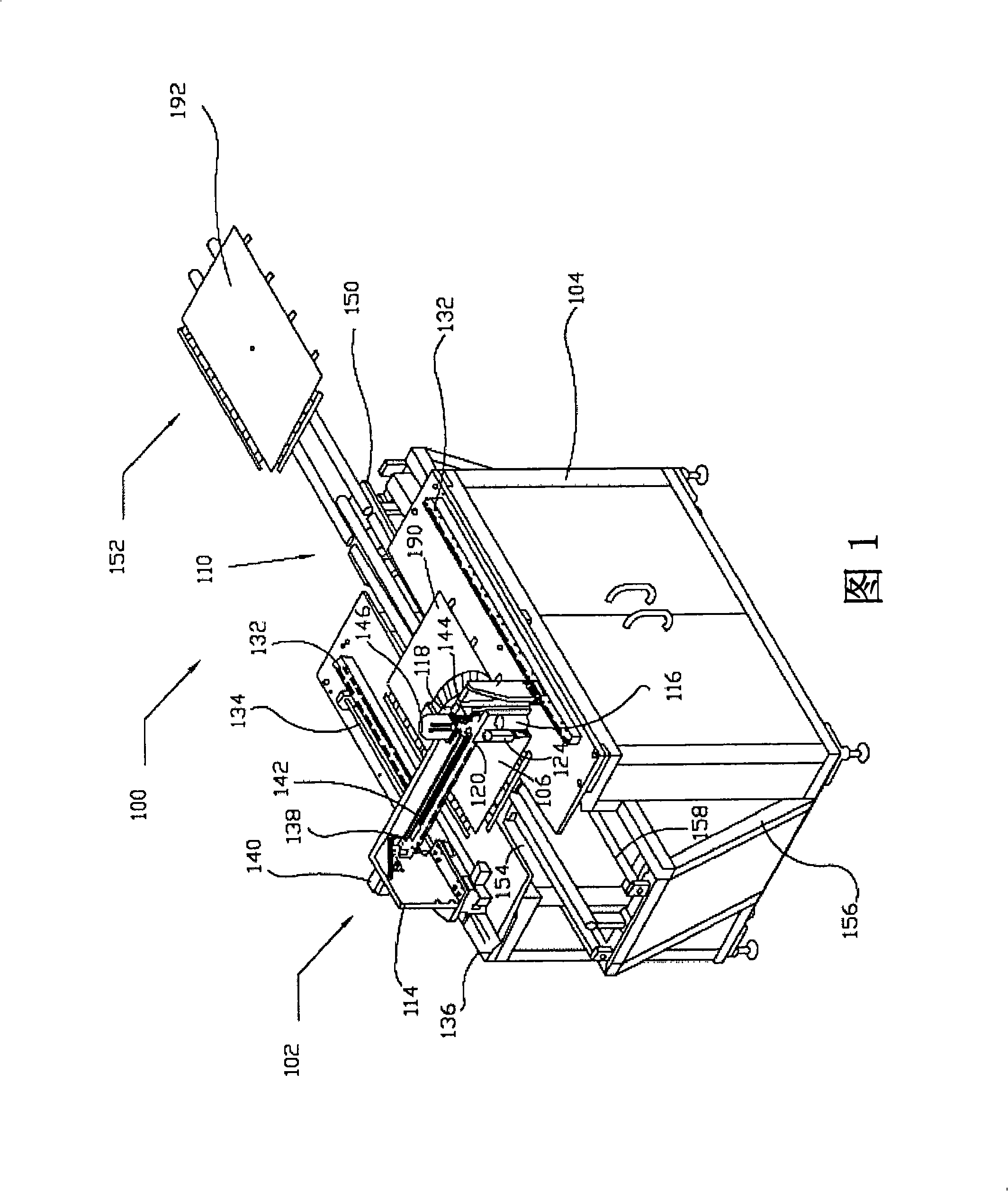
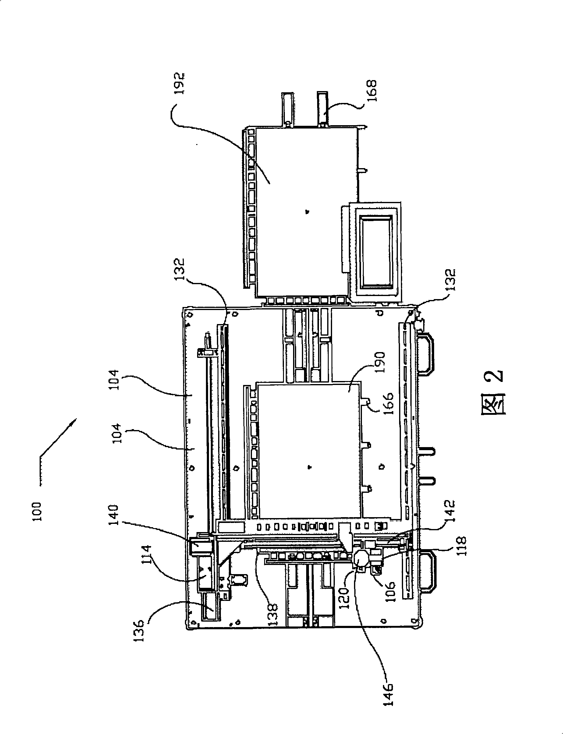
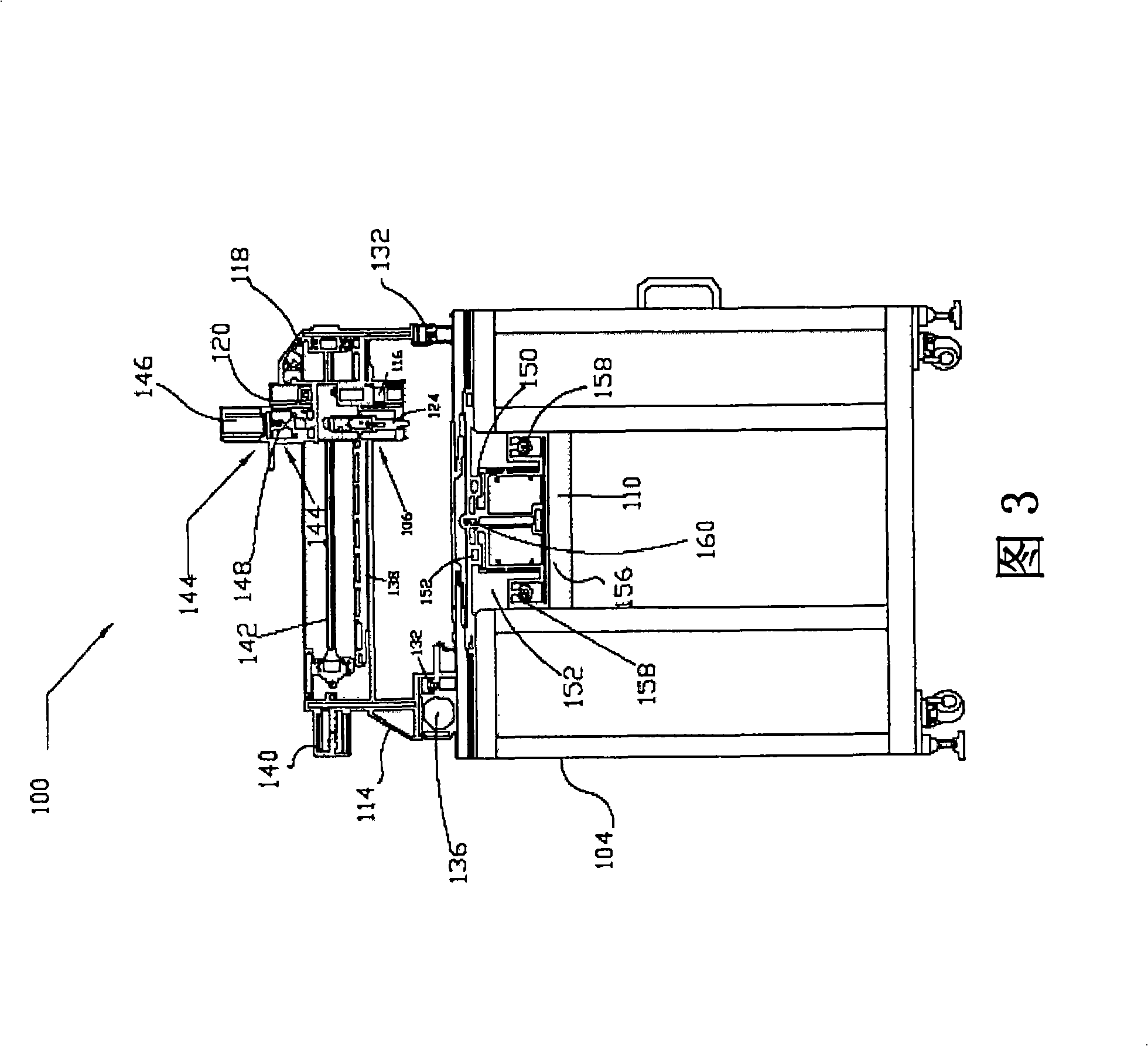
The invention discloses an automatic gluing system with synchronous charging and discharging functions and a method thereof. The system comprises a main-body platform; a mobile device which is arranged on the main body and can make three-dimensional movements; a gluing system which is connected with the mobile device and moves within the desired gluing area through the mobile device; and a mobile bearing device which is connected with the main-body platform and has a first bearing device and a second bearing device, and the two bearing devices bear the glued work pieces and the work pieces being not glued, and the two bearing devices move simultaneously and located at the same height to ensure simultaneous charging and discharging. When the panels to be pre-glued are arranged on the mobile bearing device, the glued panels are sent out at the same time; as a result, simultaneous charging and discharging functions are achieved, the process duration is shortened and the production efficiency is improved.

Description


Claims


Application Information

Patent Timeline
Owner KROMAX INT CORP
Learn More