
Method and apparatus for acquiring projected angle in image reconstruction

An acquisition method and image reconstruction technology, which are applied in the fields of radiological diagnosis instruments, diagnosis, and applications, can solve the problems of inability to obtain the projection angle, high cost of CT machines, and low image quality, so as to ensure accuracy, improve Accuracy, the effect of saving internal resources

Active Publication Date: 2008-12-24
SIEMENS SHANGHAI MEDICAL EQUIP LTD
View PDF0 Cites 14 Cited by
  • Summary
  • Abstract
  • Description
  • Claims
  • Application Information

AI Technical Summary

Problems solved by technology

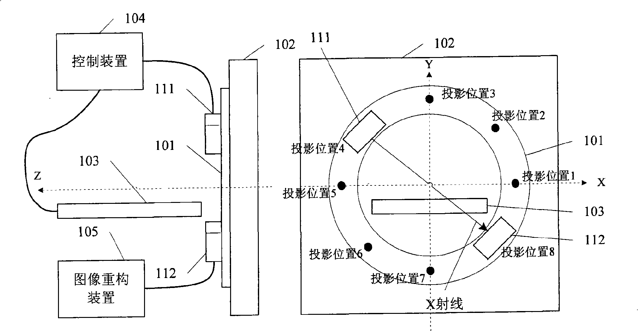
[0014] However, in practical applications, the tube 111 needs to emit at least thousands of X-rays during each round of scanning, that is, to realize image reconstruction based on position triggering, it is necessary to set thousands of sensors with an equal number for all projection positions, Make the cost of CT machine very high
[0015] It can be seen that in the existing CT image reconstruction, the accurate projection angle cannot be obtained at a low cost, so that the image quality obtained by image reconstruction is not high

Method used


Image

  • Method and apparatus for acquiring projected angle in image reconstruction
  • Method and apparatus for acquiring projected angle in image reconstruction
  • Method and apparatus for acquiring projected angle in image reconstruction

Examples


Embodiment 1

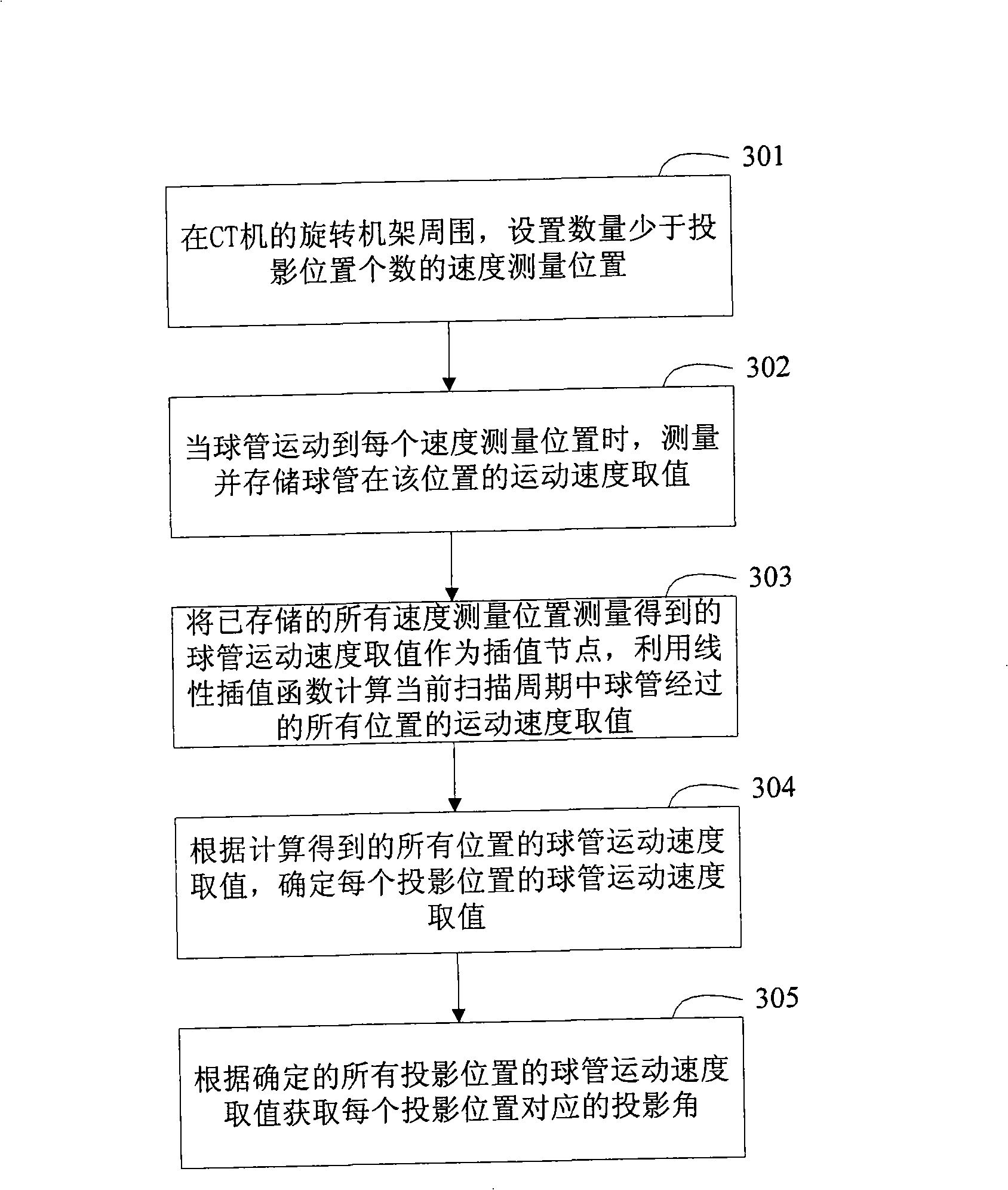
[0077] image 3 It is a flow chart of the projection angle acquisition method in the first method embodiment of the present invention. Such as image 3 As shown, the projection angle acquisition method in this embodiment includes:

[0078] Step 301 , setting velocity measurement positions whose number is less than the number of projection positions around the rotating gantry of the CT machine.

[0079] In this step, the set speed measurement positions may coincide with some projection positions, or may not coincide with all projection positions; the speed measurement positions may be evenly distributed around the rotating frame, or may be unevenly distributed.

[0080] Step 302, when the ball tube moves to each speed measurement position, measure and store the moving speed value of the ball tube at this position.

[0081] In this step, the moving speed of the ball tube at the corresponding position can be measured by devices such as sensors; the scanning method in this embodi...

Embodiment 2

[0098] Figure 6 It is a flow chart of the projection angle acquisition method in the second method embodiment of the present invention. Such as Figure 6 As shown, the projection angle acquisition method in this embodiment includes:

[0099] Step 601 , setting velocity measurement positions whose number is less than the number of projection positions around the rotating gantry of the CT machine.

[0100] In this step, the set speed measurement positions may coincide with some projection positions, or may not coincide with all projection positions; the speed measurement positions may be evenly distributed around the rotating frame, or may be unevenly distributed.

[0101] Step 602, when the ball tube moves to each speed measurement position, measure the value of the moving speed of the ball tube at this position.

[0102] In this step, the moving speed of the ball tube at the corresponding position can be measured by means of a sensor or the like.

[0103] Step 603, use th...

Embodiment 3

[0114] Figure 7 It is a flow chart of the projection angle acquisition method in the third embodiment of the method of the present invention. Such as Figure 7 As shown, the projection angle acquisition method in this embodiment includes:

[0115] Step 701 , setting velocity measurement positions whose number is less than the number of projection positions around the rotating gantry of the CT machine.

[0116] In this step, the set speed measurement positions may coincide with some projection positions, or may not coincide with all projection positions; the speed measurement positions may be evenly distributed around the rotating frame, or may be unevenly distributed.

[0117] Step 702, when the ball tube moves to each speed measurement position, measure the value of the moving speed of the ball tube at this position.

[0118] In this step, the moving speed of the ball tube at the corresponding position can be measured by devices such as sensors; the scanning method in thi...


PUM


Abstract

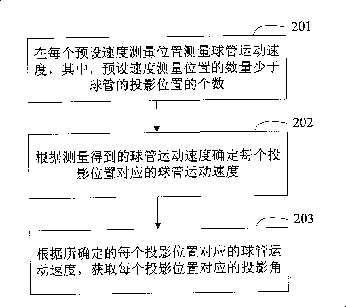
The present invention discloses a projection angle acquisition method in the image reconstruction and a projection angle acquisition device for the image reconstruction. The present invention measures the moving speed of a bulb tube in the preset speed position of the moving track of the bulb tube, determines the moving speed of each projection position according to the measured moving speed of the bulb tube and acquires the corresponding projection angle of each projection position. Compared with the prior time-triggered scanning process, the present invention increases the accuracy of the projection angle; compared with the prior position-triggered scanning process, the present invention not only increases the accuracy of the projection angle but also reduces the realization cost. In addition, the moving speed of the bulb tube is premeasured and stored so as not to redetermine the speed of the projection position in each scanning process under the condition that the moving speed of the bulb tube has no great change, thus saving the internal resources of the CT machine; or the measurement of each scanning period further ensures the accuracy of the moving speed of each projection position, thus ensuring the accuracy of the projection angle.

Description

technical field [0001] The invention relates to computerized tomography (CT) image reconstruction technology, in particular to a projection angle acquisition method in CT image reconstruction and a projection angle acquisition device for CT image reconstruction. Background technique [0002] In the process of image reconstruction, generally, the information of the target object can be collected from multiple angles first, and then the image reconstruction of the target object can be performed according to the information collected from multiple angles. [0003] Image reconstruction has been widely used in various technical fields, such as CT. figure 1 It is a structural schematic diagram of an existing CT machine. Such as figure 1 As shown, the existing CT machine at least includes: a rotating gantry 101 , a stand 102 , an examination bed 103 , a control device 104 and an image reconstruction device 105 . [0004] The rotating frame 101 is a ring structure, installed on t...

Claims


Application Information

Patent Timeline
Patent Type & Authority Applications(China)
IPC IPC(8): A61B6/03H05G1/26G06F19/00
CPCA61B6/032A61B6/547
Inventor 王薇泰戈棋徐晓东
Owner SIEMENS SHANGHAI MEDICAL EQUIP LTD
Learn More