
Layered deformation observation method and apparatus for deep part of groundwork

An observation device and a part-layer technology are applied in the deformation observation device for realizing the deformation observation method of the deep part of the foundation, the device for the observation of the deformation of the collapsible loess foundation, and the field of the deformation observation of the deep part of the foundation, which can solve the problem of low precision and high precision of the instrument. It is difficult to control and cannot meet the high-precision requirements of foundation deformation, so as to achieve the effects of accurate and reliable observation method, convenient burying and simple structure

Inactive Publication Date: 2008-12-10
NORTHWEST RES INST CO LTD OF C R E C
View PDF0 Cites 12 Cited by
  • Summary
  • Abstract
  • Description
  • Claims
  • Application Information

AI Technical Summary

Problems solved by technology

[0004] (1) Deformation observation instruments are usually deployed on the surface or shallow of the foundation, but not in the deep part of the foundation. They can only observe the deformation of the surface and shallow layers of the foundation, but cannot observe the deep deformation of the foundation, and cannot effectively judge collapsible loess Lower limit depth;
[0005] (2) When the displacement meter is used to observe the deformation of the foundation, although the accuracy is high, it is not easy to control the accuracy due to the influence of the water immersion in the test pit, and it is impossible to observe the deep deformation of the foundation;
[0006] (3) The magnetic ring subsidence instrument can be used to measure the layered deformation of the foundation, but the accuracy of this type of instrument is low, only reaching the cm level, which cannot meet the high-precision requirements of the foundation deformation, and it is impossible to observe the deep part of the foundation after being immersed in water in the test pit

Method used

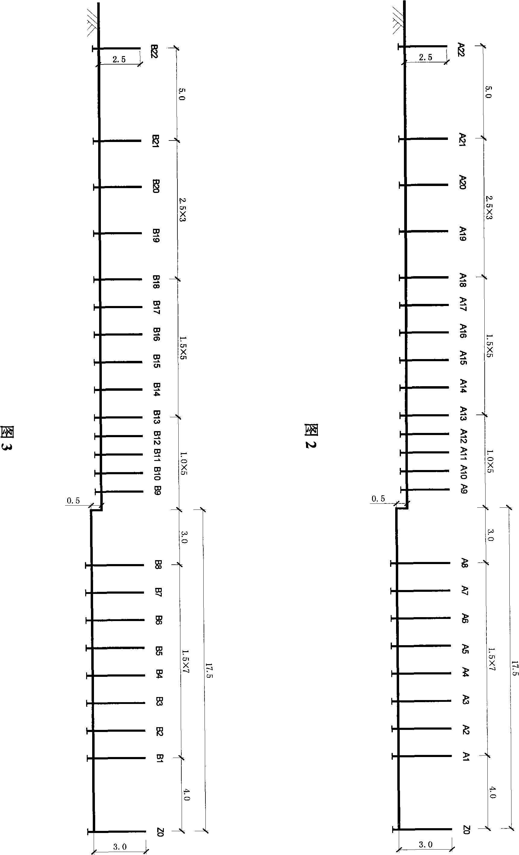

Image

  • Layered deformation observation method and apparatus for deep part of groundwork
  • Layered deformation observation method and apparatus for deep part of groundwork
  • Layered deformation observation method and apparatus for deep part of groundwork

Examples


Embodiment Construction

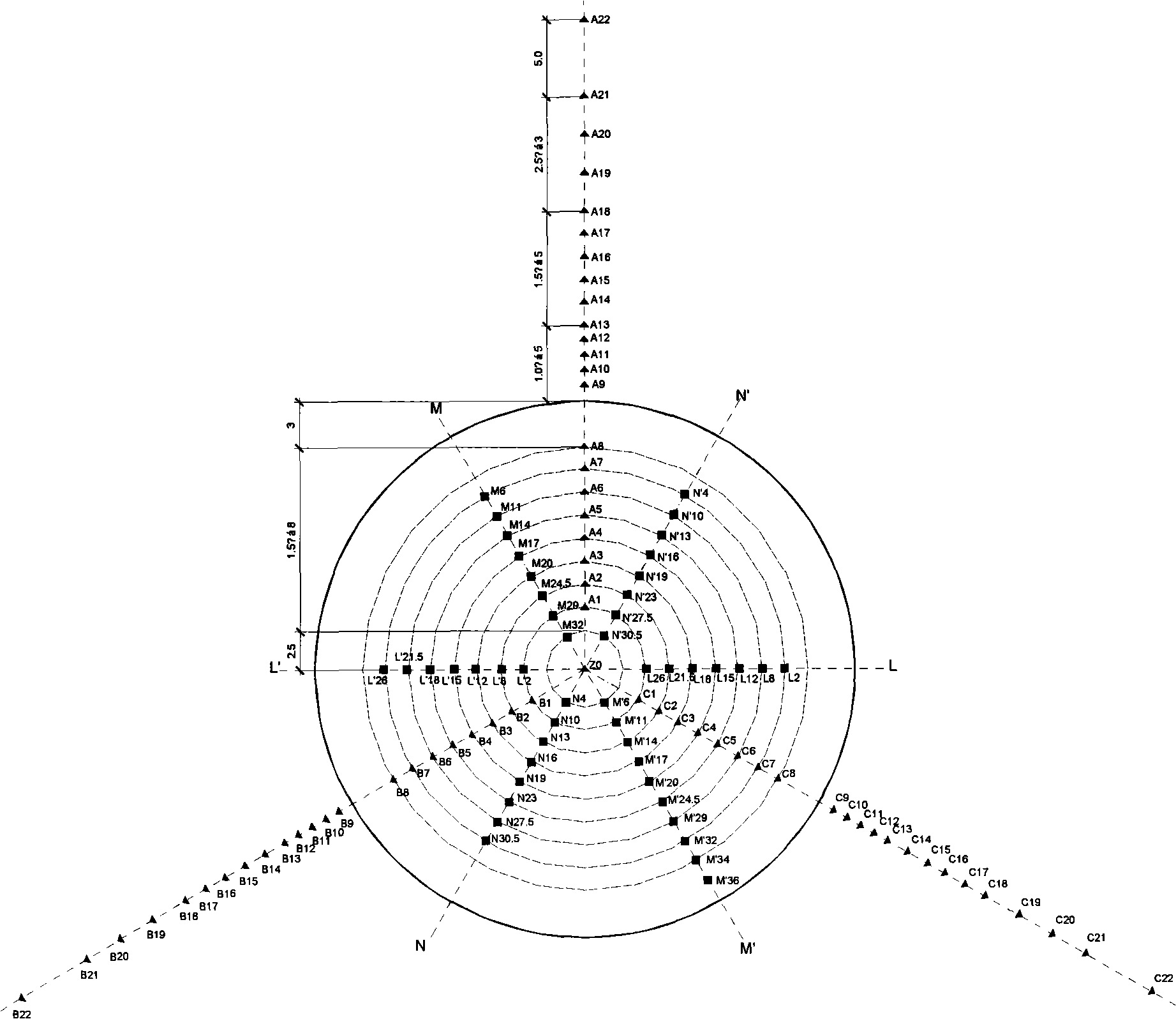
[0039] Taking Zhengxi Passenger Dedicated Line DK300+800 test point as an example below, the present invention will be further described.

[0040] (1) Excavation of test pit

[0041] Judging from the data of exploratory wells, the lower limit depth of the self-weight collapsible loess layer of the site is 31m. After comprehensive consideration of various conditions, the diameter of the flooding test pit is determined to be 35m; the design depth of the test pit is 50cm, and gravel with a thickness of 10cm is laid on the bottom of the pit , the particle size is 2-3cm.

[0042] (2) Arrangement and embedding of shallow punctuation points

[0043] Arrange a shallow punctuation point in the center of the test pit, 4.0m from the center of the test pit, radially arranged in three horizontal directions symmetrical to the edge of the pit (that is, the relative angle is 120°, which are respectively recorded as direction A, direction B, and direction C) Shallow punctuation points of gro...


PUM


Abstract

The invention provides a method for observing the layered deformation of deep parts of foundations. The method adopts an observation mode combining shallow punctuation with deep punctuation, which can observe the deformation of a surface layer and a shallow layer of an experimental foundation, carry out layered observation to the layered deformation of the deep part of the foundation and accurately observe the layered deformation of the deep part of the foundation. The method can achieve the aim of omni-directionally observing the experimental foundation, and can accurately capture the horizontal and vertical deformation range of the foundation and determine the lower limit depth of collapsible loess, so as to provide powerful technical support for determining foundation treatment depth, treatment range and the negative friction range of a pile foundation.

Description

technical field [0001] The invention belongs to the technical field of civil engineering, and relates to a method for observing deep sub-layer deformation of a foundation, in particular to a device for observing the deformation of a collapsible loess foundation, which is suitable for layered observation of the deformation of the deep part of the foundation in field immersion tests. Accurately observe the deep deformation of the foundation, and can accurately capture the lower limit depth of collapsible loess, the horizontal and vertical deformation range of the foundation. The invention also relates to a deformation observation device for realizing the deformation observation method of the deep foundation layer. Background technique [0002] Collapsible loess is an unsaturated underpressure compact soil with large pores and vertical joints. Under low natural humidity, its compressibility is low and its strength is high; but when it is soaked in water, the strength of the so...

Claims


Application Information

Patent Timeline
IPC IPC(8): E02D1/02
Inventor 王小军楚华栋熊治文达益正米维军屈耀辉武小鹏杨印海魏永梁
Owner NORTHWEST RES INST CO LTD OF C R E C
Learn More