
Sole massage machine

A technology of pressing sticks and movements, which is applied to kneading massage appliances, auxiliary products for massage, instruments for pressing reflex points, etc., and can solve the problem of increasing the number of parts of foot massage machines

Inactive Publication Date: 2008-08-20
MATSUSHITA ELECTRIC WORKS LTD
View PDF2 Cites 1 Cited by
  • Summary
  • Abstract
  • Description
  • Claims
  • Application Information

AI Technical Summary

Problems solved by technology

However, a group with a plurality of finger pressure sticks 91 will increase the number of parts of the foot massage machine, or may not be able to cope with the size of feet that vary greatly from adults to children.

Method used


Image

  • Sole massage machine
  • Sole massage machine
  • Sole massage machine

Examples


Embodiment Construction

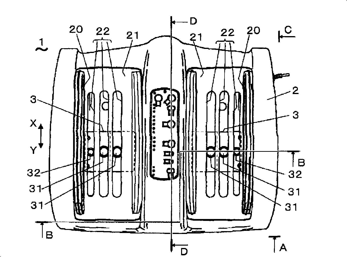
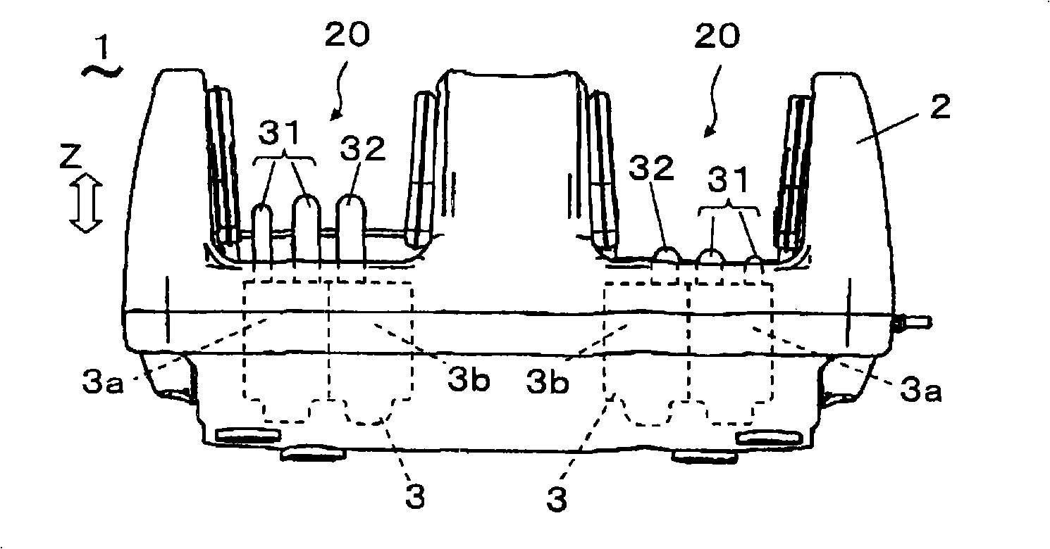
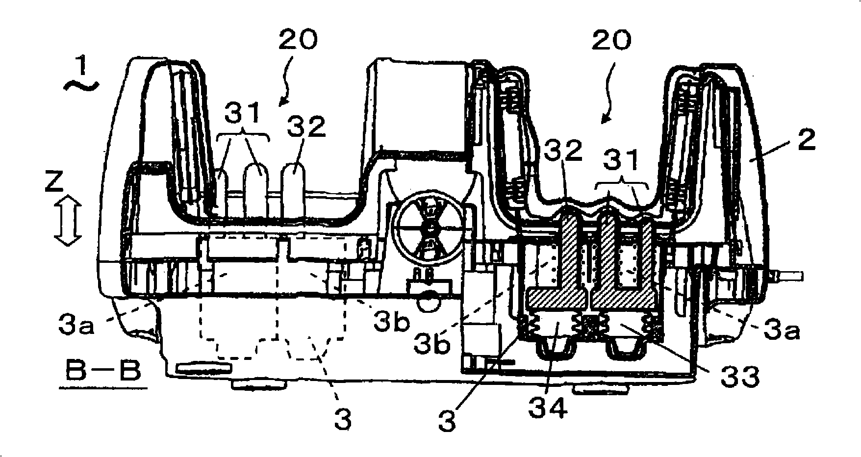
[0030] Next, a foot massager according to an embodiment of the present invention will be described with reference to the drawings. Figure 1 ~ Figure 4B Represent foot massage machine 1 of the present invention, Figure 5 , 6 Indicates the acupressure part 3 of the foot massage machine 1, Figures 7A-7C , Figures 8A-8C It shows the case where the sole of the foot and the toe are massaged by the foot massager 1 . like figure 1 , 2 As shown in , 3, the foot massage machine 1 has a housing 2 with a shape larger than the size of the two feet placed together, in which a pair of left and right finger-pressing parts 3 are built, and the finger-pressing parts 3 have a finger-pressing stick 31 , 32.

[0031] The upper surface of the casing 2 is provided with left and right recesses 20 for placing both feet and a switch panel at the center for setting the massage function. A plurality of slits 22 along the toe direction (front-rear direction, arrow XY direction) are provided on...


PUM


Abstract

This foot massage machine can bring appropriate acupressure feeling regardless of the size of the feet and the position of the soles of the feet. The foot massage machine has a finger-pressing part (3) corresponding to the left and right feet, and the finger-pressing part (3) has finger-pressing sticks (31, 32). Each acupressure member (3) is driven by a motor to change the position in the front-rear direction of the sole of the foot. In the inner space (3a) of the finger-pressing part (3), two finger-pressing sticks (31), an air bag (33), and a coil spring (35) combined by the base (31a) are arranged, and the inner space (3b) is arranged with Enlarged diameter base (32a), bladder (34), helical spring (36). The acupressure stick (31) moves up and down by the action of the air bag (33), and the acupressure stick (32) moves in the up and down direction by the action of the air bag (34). The acupressure sticks (31, 32) are arranged side by side in the left-right direction of the soles of the feet for acupressure. Get massaged.

Description

technical field [0001] The present invention relates to a foot massager using an acupressure stick operated by an air bag. Background technique [0002] Conventionally, there is known a foot massage machine which massages the sole of a foot using the tip of an acupressure stick. Among such massage machines are, for example, Figure 11 Acupressure member 9 models are shown. The structure of the acupressure part 9 is: in the direction of the arrow Z, three long (hereinafter referred to as the longitudinal direction Z) acupressure sticks 91 are combined by their bases 91a. Coil springs 94 are arranged to surround the respective acupressure sticks 91 , and these are accommodated in an acupressure unit box 90 which is a box with a lid. In addition, a left and right pair of acupressure members 9 is usually adopted corresponding to the left and right feet. [0003] If air is supplied to the air bag 93 from the air inlet hole not shown to inflate the air bag 93, the base portion ...

Claims


Application Information

Patent Timeline
IPC IPC(8): A61H39/04A61H7/00
CPCA61H7/001A61H39/04A61H2201/1238A61H2205/12A61H7/00
Inventor 上林正水内明广
Owner MATSUSHITA ELECTRIC WORKS LTD
Learn More