Refrigerating apparatus
A refrigeration device and refrigerant technology, applied in refrigerators, refrigeration components, refrigeration and liquefaction, etc., can solve problems such as functioning
- Summary
- Abstract
- Description
- Claims
- Application Information
AI Technical Summary
Problems solved by technology
Method used
Image

Examples
Embodiment 1
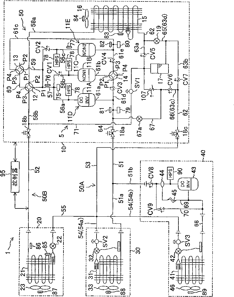
[0062] Embodiment 1 of the present invention will be described below. The refrigerant circuit diagram of the refrigeration device 1 involved in the present embodiment 1 is as follows: figure 1 shown. This refrigerating device 1 is installed in a convenience store and is used for cooling the refrigerated display case and the refrigerated display case, and supplying air and cold air in the store.
[0063] The refrigerating device 1 includes: an outdoor unit (heat source side unit) 10, an indoor unit (second use side unit) 20, a refrigerating unit (first use side unit) 30, and a refrigerating unit (first use side unit) 40, The units 10, 20, 30, 40 are connected by gas-side connecting pipes 51, 52 and liquid-side connecting pipes 53, 54, 55 to constitute a refrigerant circuit 50 of a vapor compression refrigeration cycle.
[0064] The gas side connecting pipes 51 and 52 are composed of a first gas side connecting pipe (low-pressure gas pipe) 51 connecting the outdoor unit 10 , ...
Embodiment 2
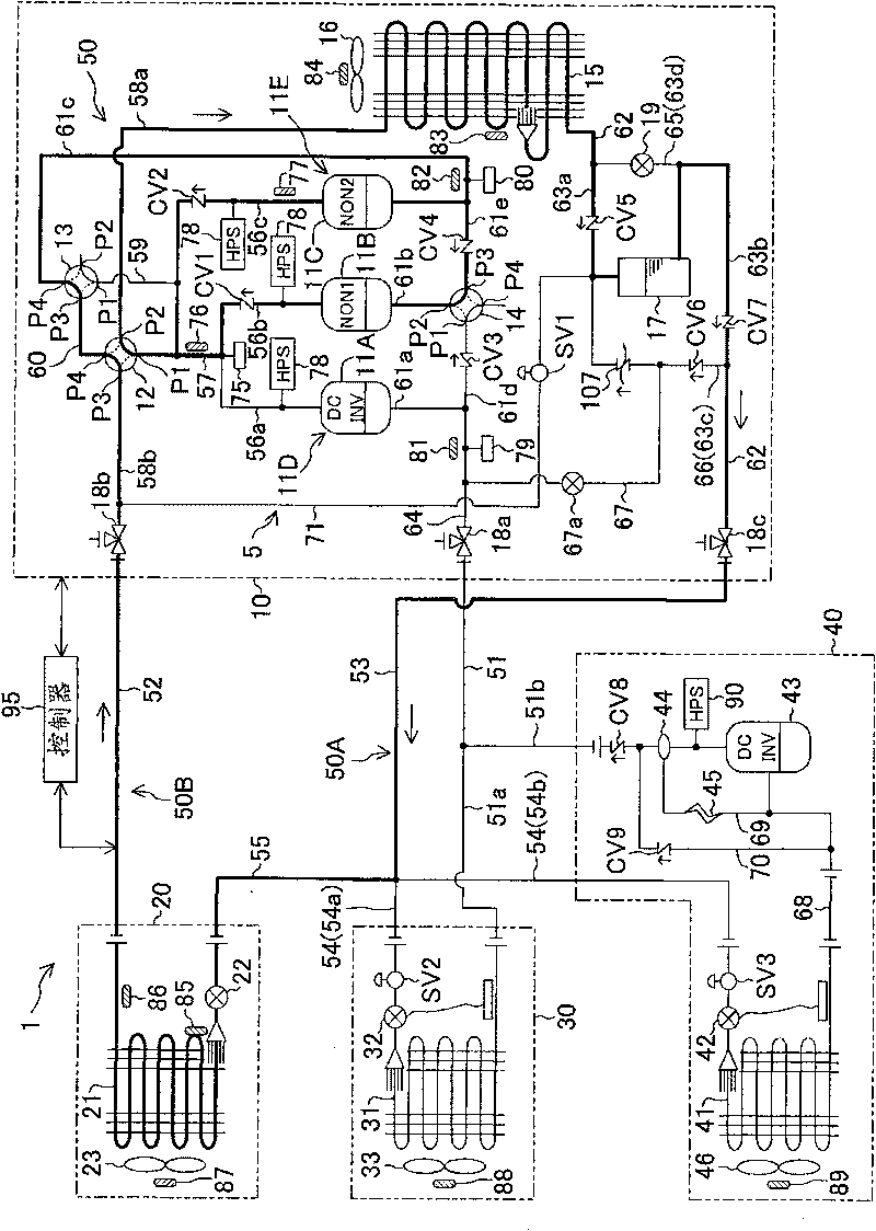
[0171] Embodiment 2 of the present invention will be described below. The refrigerant circuit diagram of the refrigerating device 1 related to this embodiment 2 is as follows Figure 11 shown. The refrigerating device 1 of this embodiment 2 is different from the above-mentioned embodiment 1 in that the hot gas bypass pipe 71 is not provided with a solenoid valve SV1, and the second four-way reversing valve 13 as a communication mechanism constitutes the refrigerant return mechanism 5 .
[0172] The operation of returning the liquid refrigerant in liquid receiver 17 to the circulation path in the first heating and cooling operation will be described below. In the refrigeration system 1 of the second embodiment, when the degree of superheat of the refrigerant flowing through the suction pipe 61a detected from the detection value of the low-pressure pressure sensor 79 and the detection value of the suction temperature sensor 81 becomes a predetermined value or more, Then ...
Embodiment 3
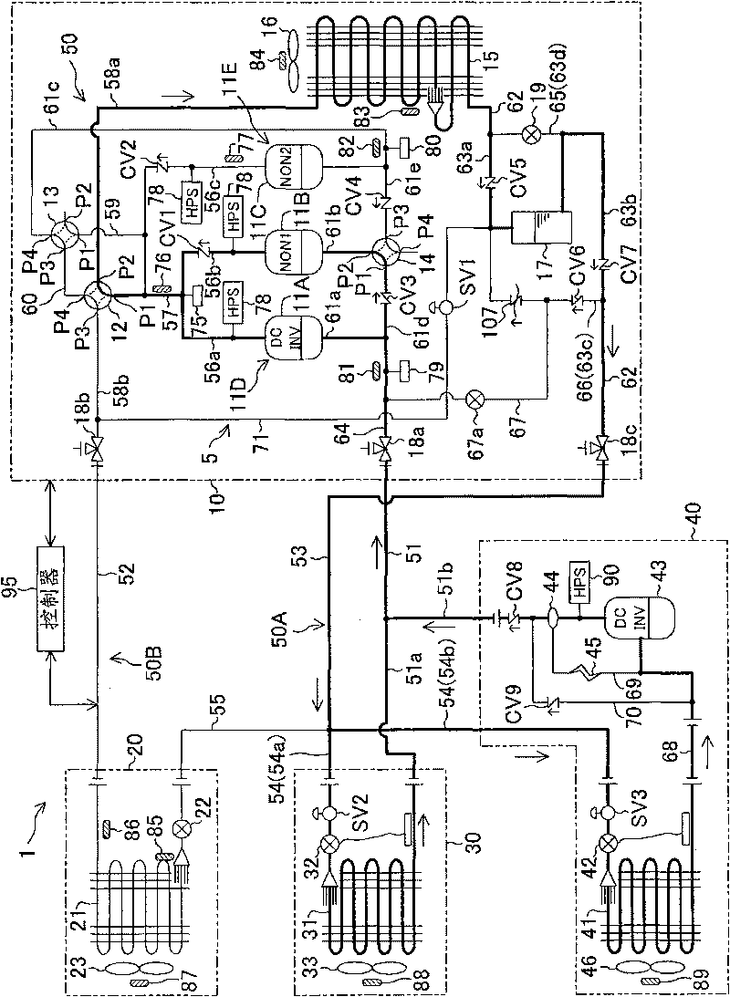
[0177] Embodiment 3 of the present invention will be described below. The refrigerant circuit diagram of the refrigerating device 1 related to this embodiment 3 is as follows: Figure 12 shown. The refrigeration system 1 of the third embodiment is different from the first embodiment in that the hot gas bypass pipe 71 and the solenoid valve SV1 are not provided, and in the connection position of the liquid injection pipe 67 .
[0178] One end of the liquid injection pipe 67 is connected to the connecting portion of the suction pipe 61a and the low-pressure air pipe 64, and the other end of the liquid injection pipe 67 is connected to the connection point of the auxiliary liquid pipe 65 in the outdoor liquid pipe 62 and the closing valve 18c side and Between the liquid receiver 17. The liquid injection pipe 67 is a communication pipe for connecting the liquid receiver 17 to the suction side of the compression mechanism 11D, and constitutes the refrigerant return mechanism...
PUM
 Abstract
Description
Claims
Application Information
 - R&D
- Intellectual Property
- Life Sciences
- Materials
- Tech Scout
- Unparalleled Data Quality
- Higher Quality Content
- 60% Fewer Hallucinations
Browse by: Latest US Patents, China's latest patents, Technical Efficacy Thesaurus, Application Domain, Technology Topic, Popular Technical Reports.
© 2025 PatSnap. All rights reserved.Legal|Privacy policy|Modern Slavery Act Transparency Statement|Sitemap|About US| Contact US: help@patsnap.com