Foldaway frame
A technology for folding a frame and a locking device, applied in the field of folding frames, can solve the problem that the frame cannot be folded, and achieve the effects of compact structure, improved performance and small volume
- Summary
- Abstract
- Description
- Claims
- Application Information
AI Technical Summary
Problems solved by technology
Method used
Image
Examples
Embodiment 1
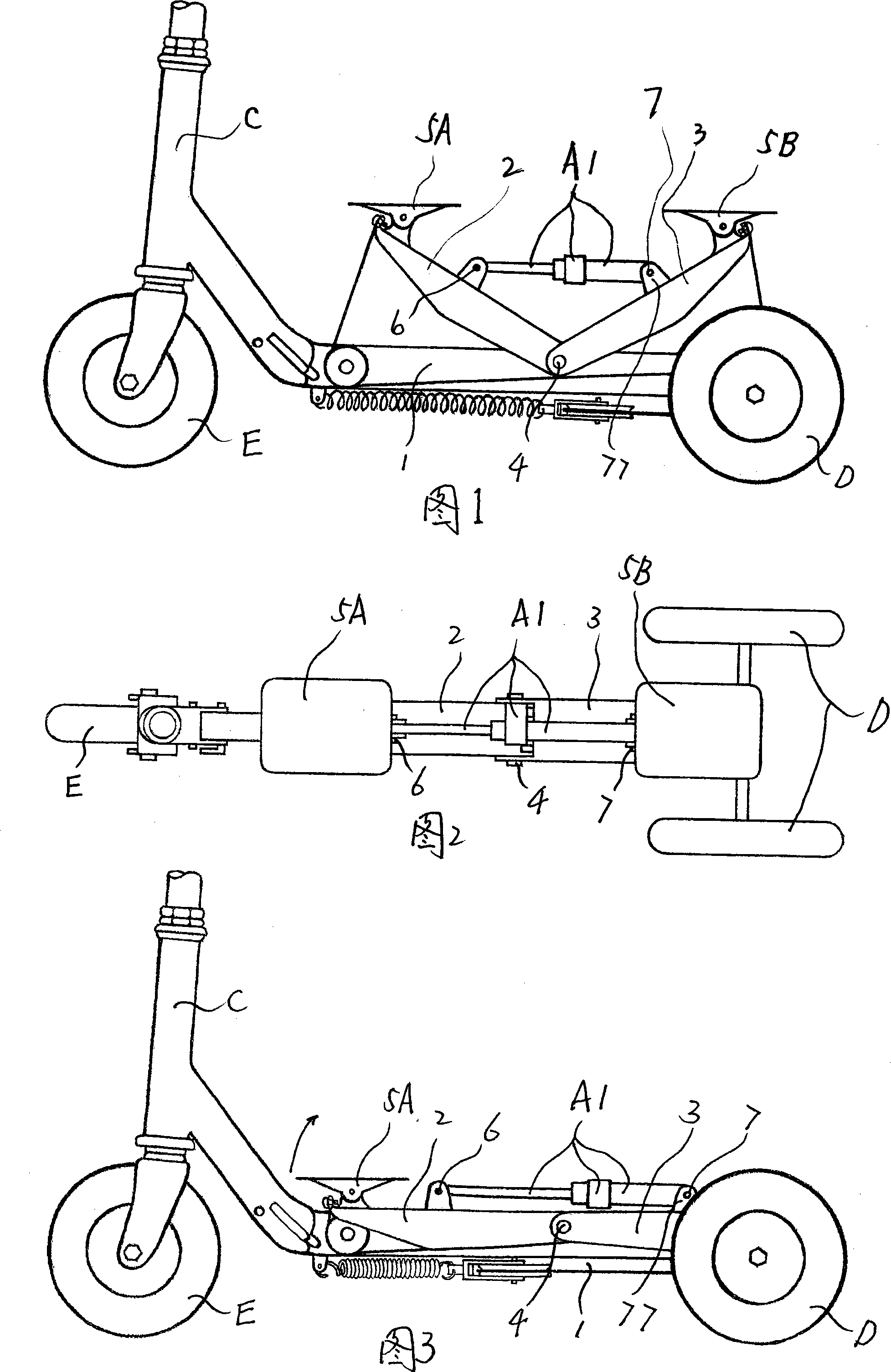
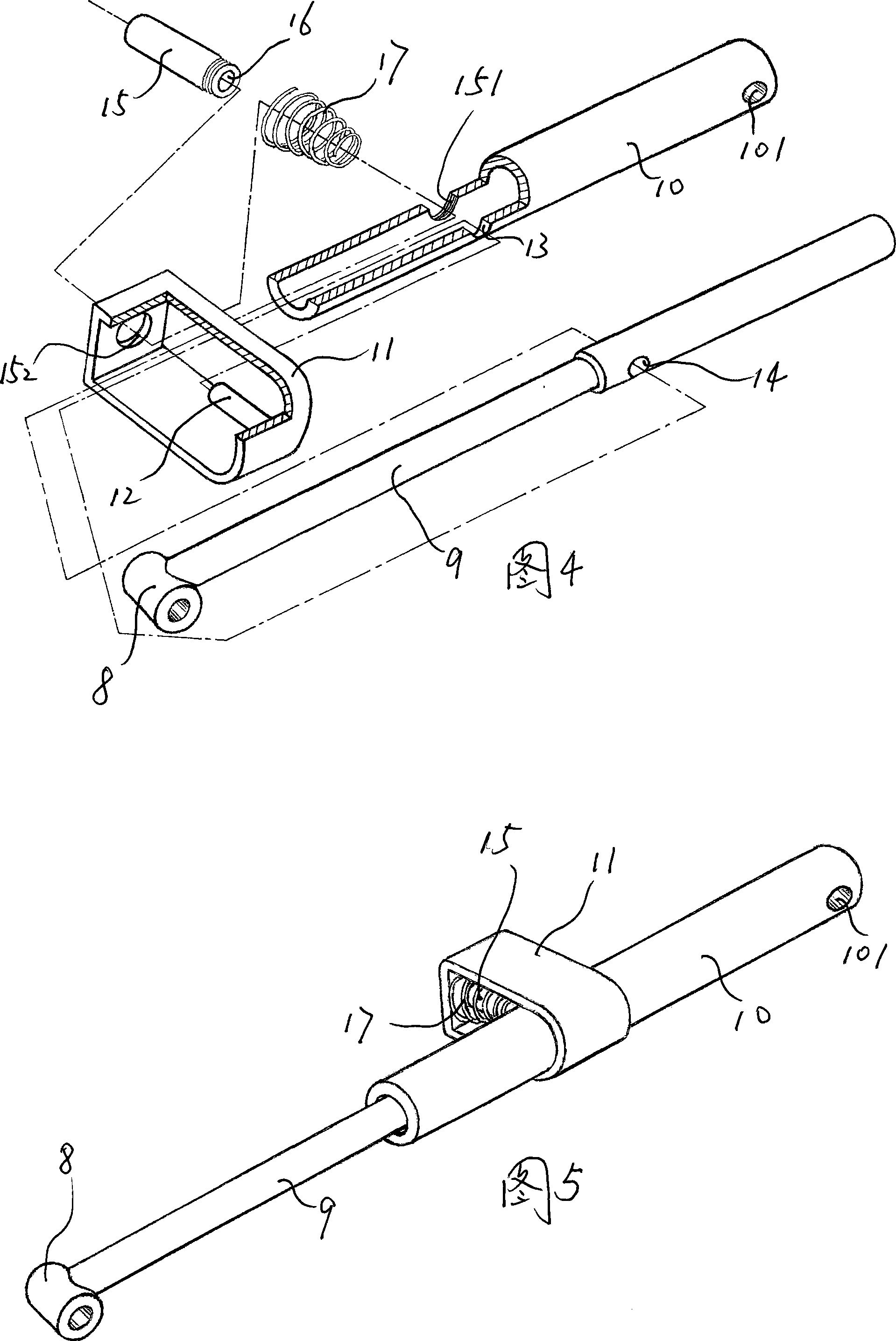
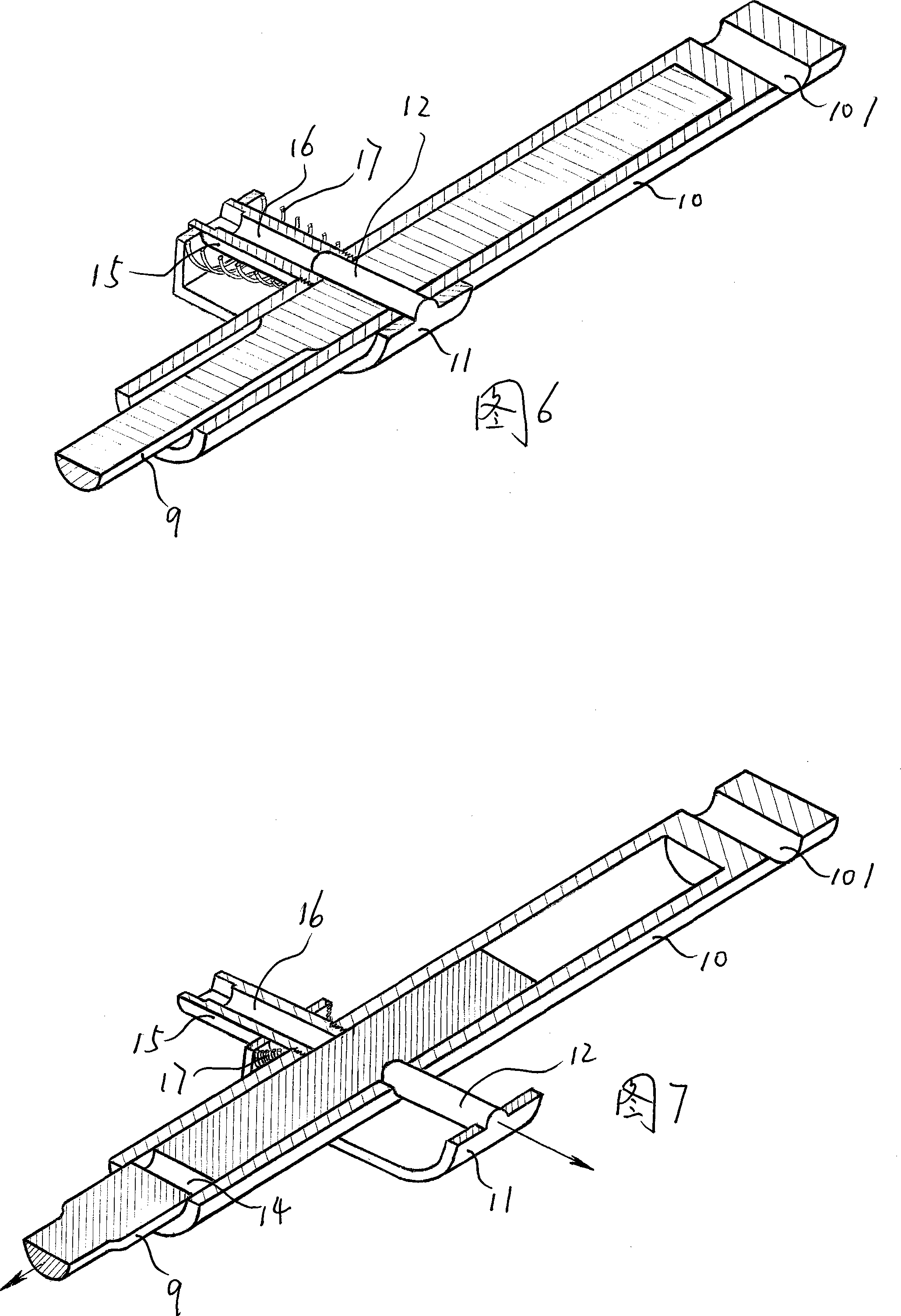
[0051] As shown in Figure 1, Figure 2 and Figure 3, the rear end of the front pedal 2, the front end of the rear pedal 3 and the middle part of the beam 1 are jointly hinged on the same hinge shaft 4, and the front end of the locking device A1 is connected to the front The middle part of the pedal 2 is hinged to the hinge pin 6 , and the rear end of the locking device A1 is hinged to the hinge pin 7 with the hinge ear 77 provided on the middle part of the rear pedal 3 . The folding vehicle frame of the present invention is a part of the folding vehicle. When the folding vehicle is assembled into a complete vehicle, the front end of the crossbeam 1 is foldably connected to the rearward and downward extension tube of the steering mechanism C; the rear end of the crossbeam 1 is connected to the The axle of rear wheel D is fixedly connected. The locking device A1 in the locked state limits the relative position between the front and rear pedals, so that the angle between the front...
Embodiment 2
[0059] As shown in Figures 10 to 13, the overall structure of the folding frame of this embodiment is the same as that of Embodiment 1 of the folding frame, and the rear end of the front pedal 2, the front end of the rear pedal 3, and the middle part of the beam 1 are jointly hinged at three places. Between the same hinge shaft 4, the front pedal 2 and the rear pedal 3, a locking device for controlling the angle change between the front pedal 2 and the rear pedal 3 is provided. The front end of the crossbeam 1 is also foldably connected to the rearward and downward extension tube of the steering mechanism C; the rear end of the crossbeam 1 is also fixedly connected to the axle of the rear wheel D. The difference is that the structure of the locking device A2 in Embodiment 2 is different from that of the locking device A1 in Embodiment 1. The locking device A2 is composed of a crankshaft linkage mechanism that is hinged with the front pedal 2 and the rear pedal 3 at the front an...
Embodiment 3
[0065] As shown in Figures 18 to 20, the overall structure of the foldable frame of this embodiment is the same as that of foldable frame embodiment 1 and foldable frame embodiment 2, both of which are the rear end of the front pedal 2, the front end of the rear pedal 3 and the beam. Three places in the middle of 1 are jointly hinged on the same hinge shaft 4, and a locking device for controlling the angle change between the front pedal 2 and the rear pedal 3 is provided between the front pedal 2 and the rear pedal 3. The front end of the crossbeam 1 is also foldably connected to the rearward and downward extension tube of the steering mechanism C; the rear end of the crossbeam 1 is also fixedly connected to the axle of the rear wheel D. The difference is that the locking device A3 in this embodiment 3 is different in structure from the locking devices A1 and A2 in the embodiment 1 and embodiment 2, and the locking device A3 is composed of a hook fixed on the front pedal 2 and ...
PUM
 Abstract
Description
Claims
Application Information
 - R&D
- Intellectual Property
- Life Sciences
- Materials
- Tech Scout
- Unparalleled Data Quality
- Higher Quality Content
- 60% Fewer Hallucinations
Browse by: Latest US Patents, China's latest patents, Technical Efficacy Thesaurus, Application Domain, Technology Topic, Popular Technical Reports.
© 2025 PatSnap. All rights reserved.Legal|Privacy policy|Modern Slavery Act Transparency Statement|Sitemap|About US| Contact US: help@patsnap.com


