
Picture edge intensification method and device

A technology of image edge enhancement device, applied in image enhancement, image communication, image data processing and other directions, can solve the problems of reduced brightness value and unnatural image edge enhancement

Inactive Publication Date: 2010-08-25
QUANTA COMPUTER INC
View PDF0 Cites 0 Cited by
  • Summary
  • Abstract
  • Description
  • Claims
  • Application Information

AI Technical Summary

Problems solved by technology

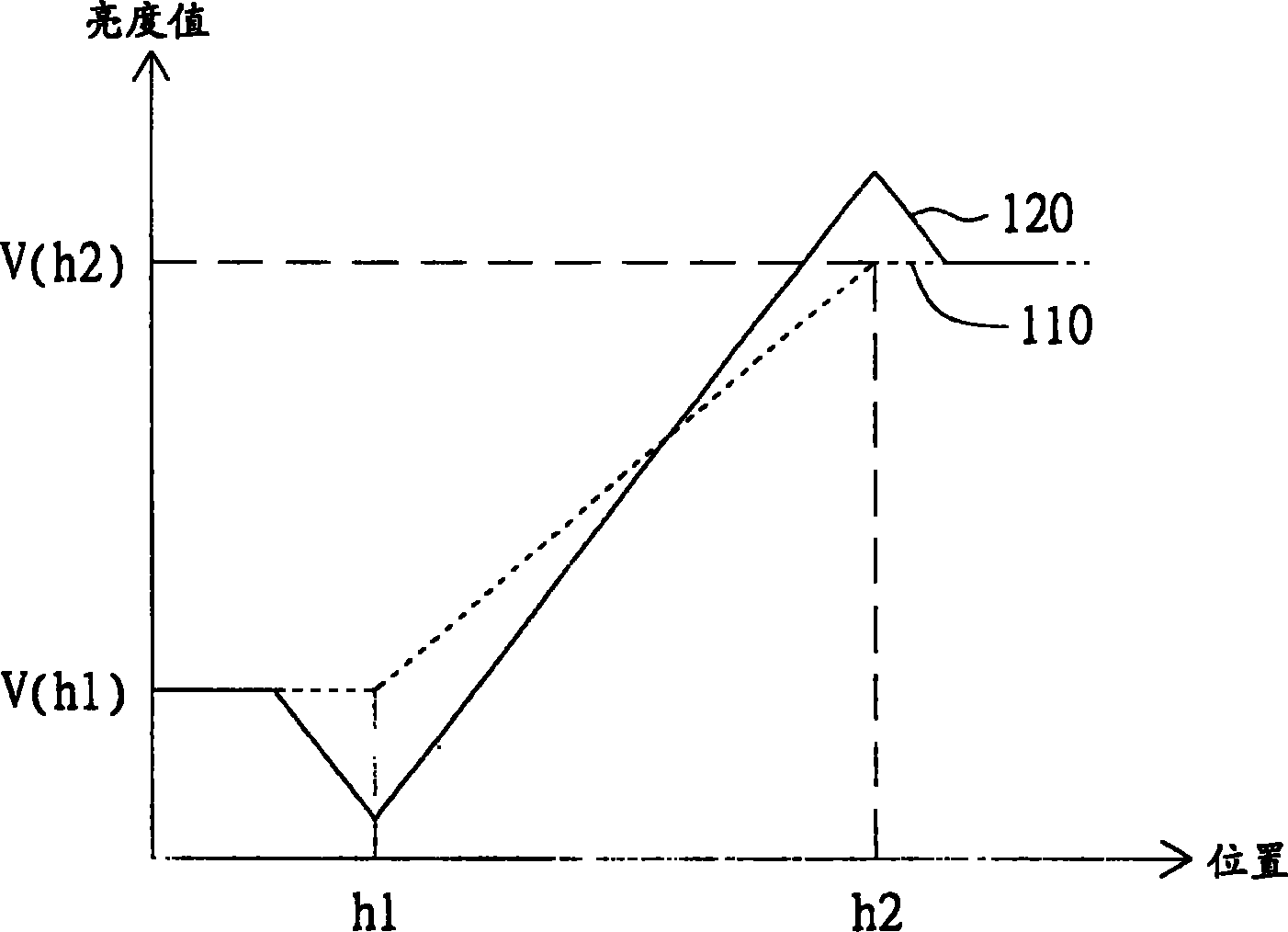
The brightness value of the pixels near the position h1 is excessively reduced, which is lower than the minimum value V(h1) of the edge of the original image, which makes the edge of the enhanced image produce a halo effect near the positions h1 and h2, which looks unnatural

Method used


Image

  • Picture edge intensification method and device
  • Picture edge intensification method and device
  • Picture edge intensification method and device

Examples


Embodiment Construction

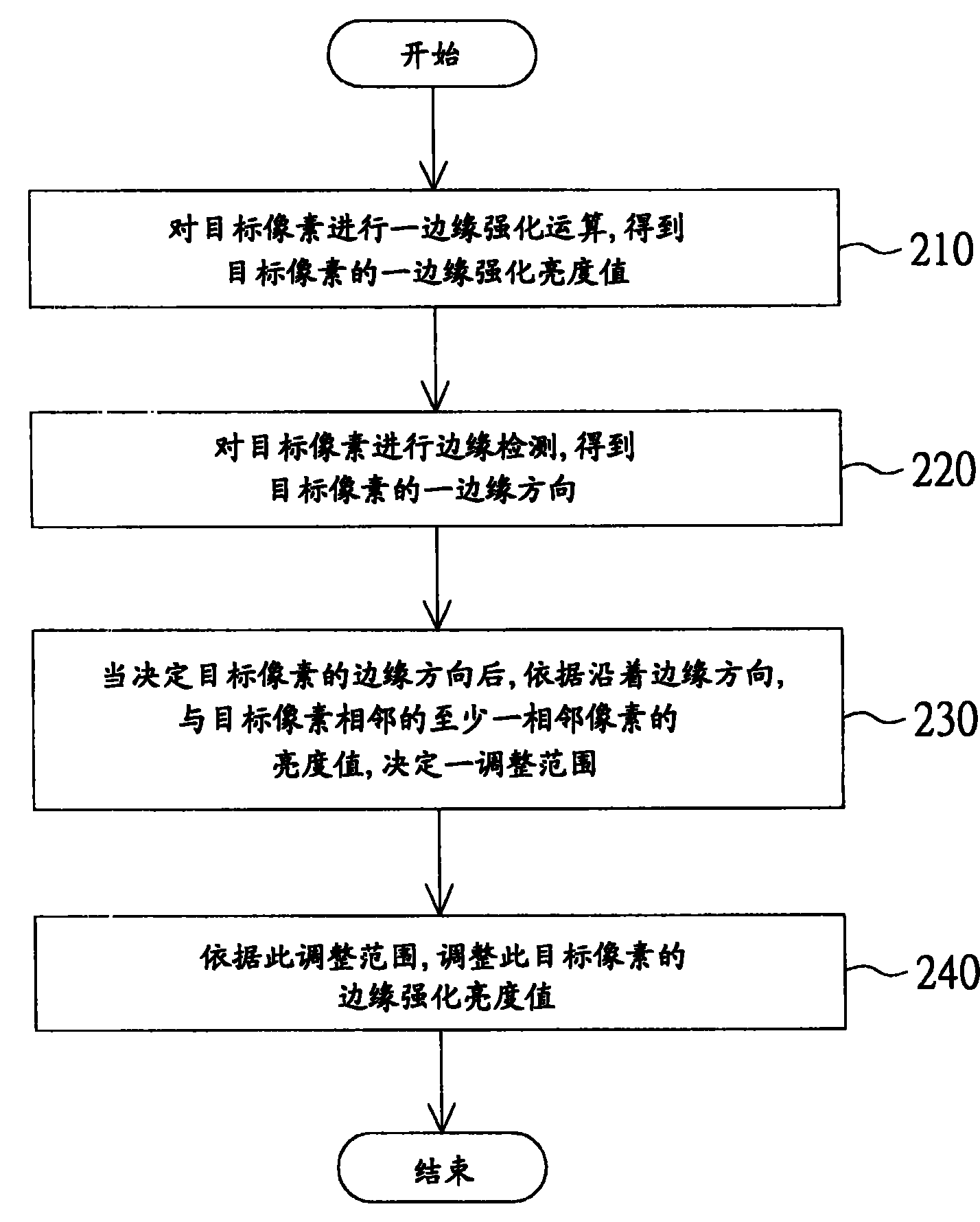
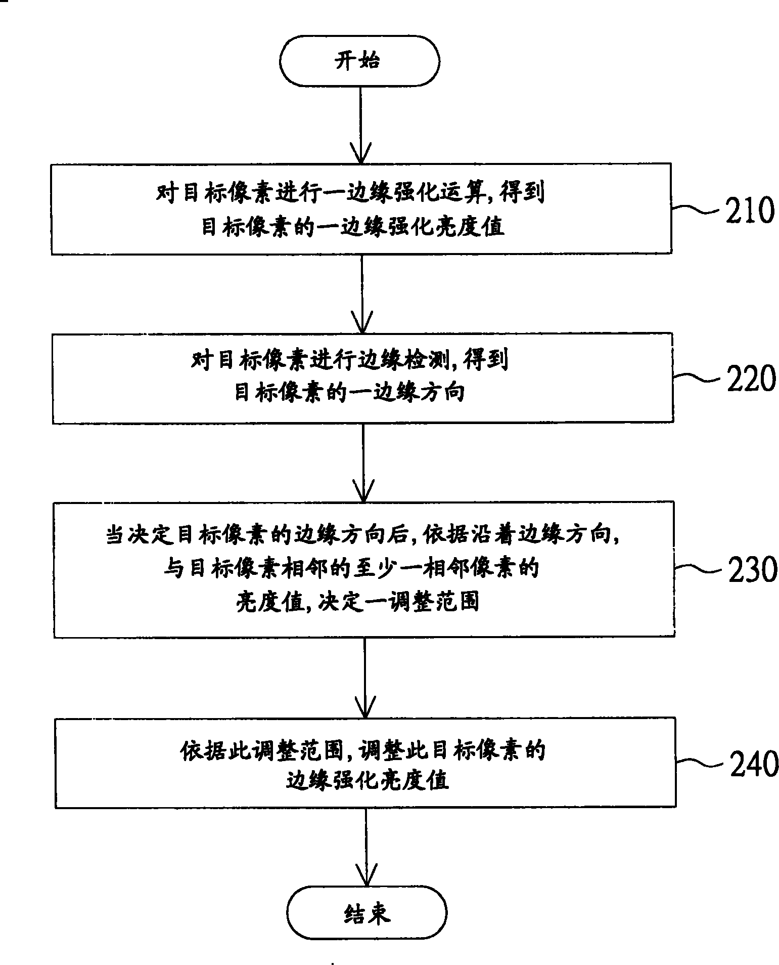
[0024] The image edge enhancement method of the embodiment of the present invention is used for adjusting the brightness of a target pixel of a digital image. The image edge enhancement method of the embodiment of the present invention performs edge boosting (edge ​​boosting or edge enhancement) on the target pixel, and after obtaining an edge enhanced luminance value, an adjustment range is determined according to the luminance values ​​of adjacent pixels near the target pixel. Then adjust the edge enhancement brightness value according to the adjustment range. If the edge enhancement brightness value is too high or too low, the edge enhancement brightness value can be decreased or increased according to the adjustment range. Therefore, while increasing the edge intensity of the target pixel, it is also possible to prevent the target pixel from producing a halo effect that is too bright or too dark. Applying the image edge enhancement method of the embodiment of the present ...


PUM


Abstract

The invention discloses an edge boosting method for images and is used to adjust the luminance of a target pixel of a digital image. The target pixel has an original luminance value. The method comprises that: the edge boosting operation is done to the target pixel to obtain an edge boosting luminance value of the target pixel. The target pixel is made an edge detection to obtain an edge direction of the target pixel. Then an adjustment range is determined according to the luminance value of at least one neighboring pixel neighboring the target pixel and along the edge direction. Then the edge boosting luminance value is adjusted according to the adjustment range to ensure that the adjusted edge boosting luminance value can not be over-bright or over-dark, the halo effect is suppressed, and the sharpness of the image edge is increased.

Description

technical field [0001] The invention relates to an image edge enhancement method, and in particular to an image edge enhancement method capable of suppressing a halo effect. Background technique [0002] Image edge enhancement technology is to adjust the contrast or brightness of the edge of the object in the display screen to make the outline of the image clear, so that the object is more obvious, and the image is clearer and clearer under the sense of the human eye. [0003] FIG. 1 is a schematic diagram of a conventional enhanced image edge, the horizontal axis is the position along a specific direction, and the vertical axis is the brightness value. Curve 110 is a relationship curve between the position of the edge of the original image along the specific direction and the brightness. Curve 120 is a relationship curve between the position of the edge of the enhanced image along the specific direction and the brightness. Wherein, the edge of the enhanced image is obtain...

Claims


Application Information

Patent Timeline
Patent Type & Authority Patents(China)
IPC IPC(8): H04N1/409H04N1/58G06T5/00
Inventor 何升峰
Owner QUANTA COMPUTER INC
Learn More