Method and device for suppressing carrier leakage

A technology for suppressing carrier waves and carrier leakage, applied in electrical components, transmission systems, etc., can solve the problems of low efficiency and high cost

Active Publication Date: 2007-11-14
SPREADTRUM COMM (SHANGHAI) CO LTD
View PDF8 Cites 24 Cited by
  • Summary
  • Abstract
  • Description
  • Claims
  • Application Information

AI Technical Summary

Problems solved by technology

[0008] In order to solve the problems of high cost and low efficiency of the above-mentioned existing carrier suppression methods, a method and device for suppressing carrier leakage are proposed, which can effectively suppress carrier leakage and improve efficiency

Method used


Image

  • Method and device for suppressing carrier leakage
  • Method and device for suppressing carrier leakage
  • Method and device for suppressing carrier leakage

Examples


Embodiment Construction

[0022] The present invention will be described in detail below in conjunction with the accompanying drawings and specific embodiments.

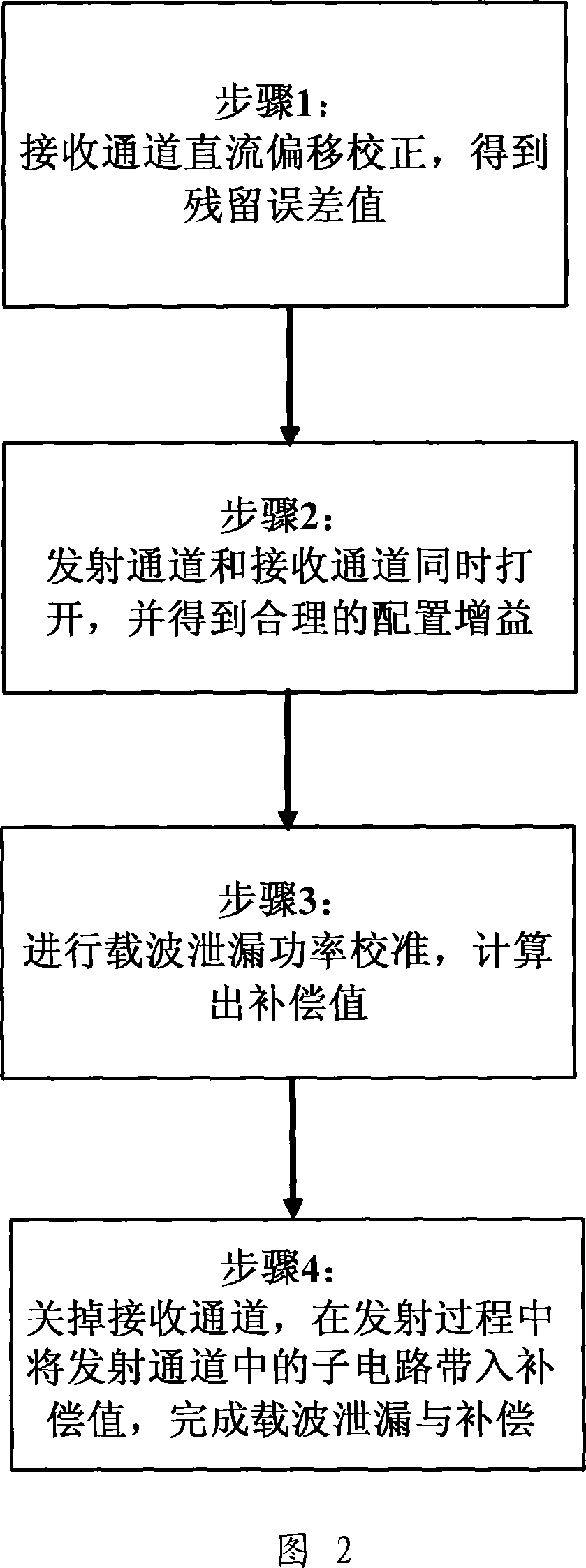
[0023] Fig. 2 is a flowchart of steps of the present invention. As shown in Figure 2, the present invention includes the following steps: Step 1, rectify the DC offset of the receiving channel to obtain the residual error value; Step 2, open the transmitting channel and the receiving channel at the same time, and obtain a reasonable configuration gain; Step 3, perform carrier Calibrate the leakage power to calculate the compensation value; step 4, turn off the receiving channel, and bring the sub-circuit in the transmitting channel into the compensation value during the transmission process to complete the carrier leakage and compensation.

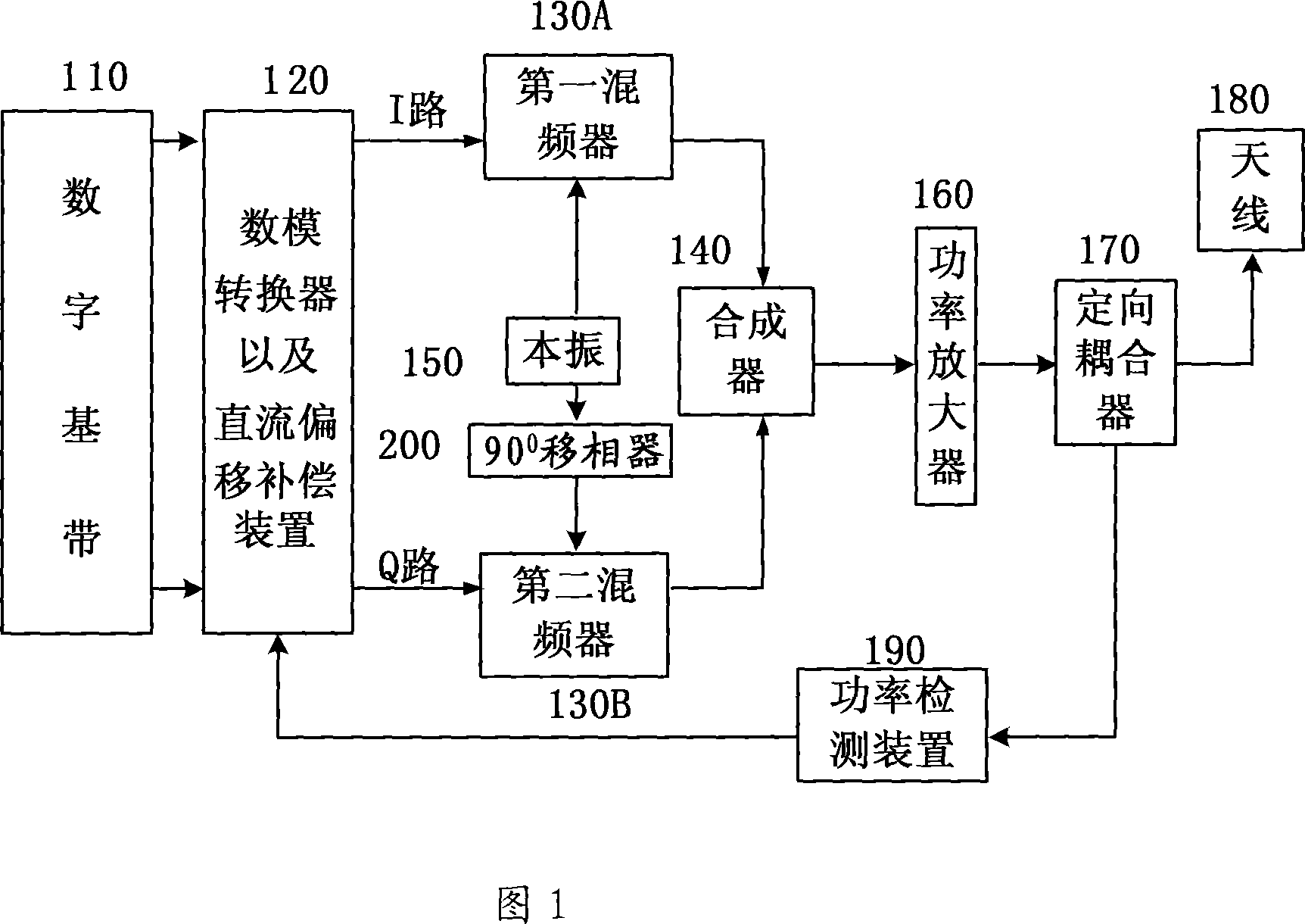
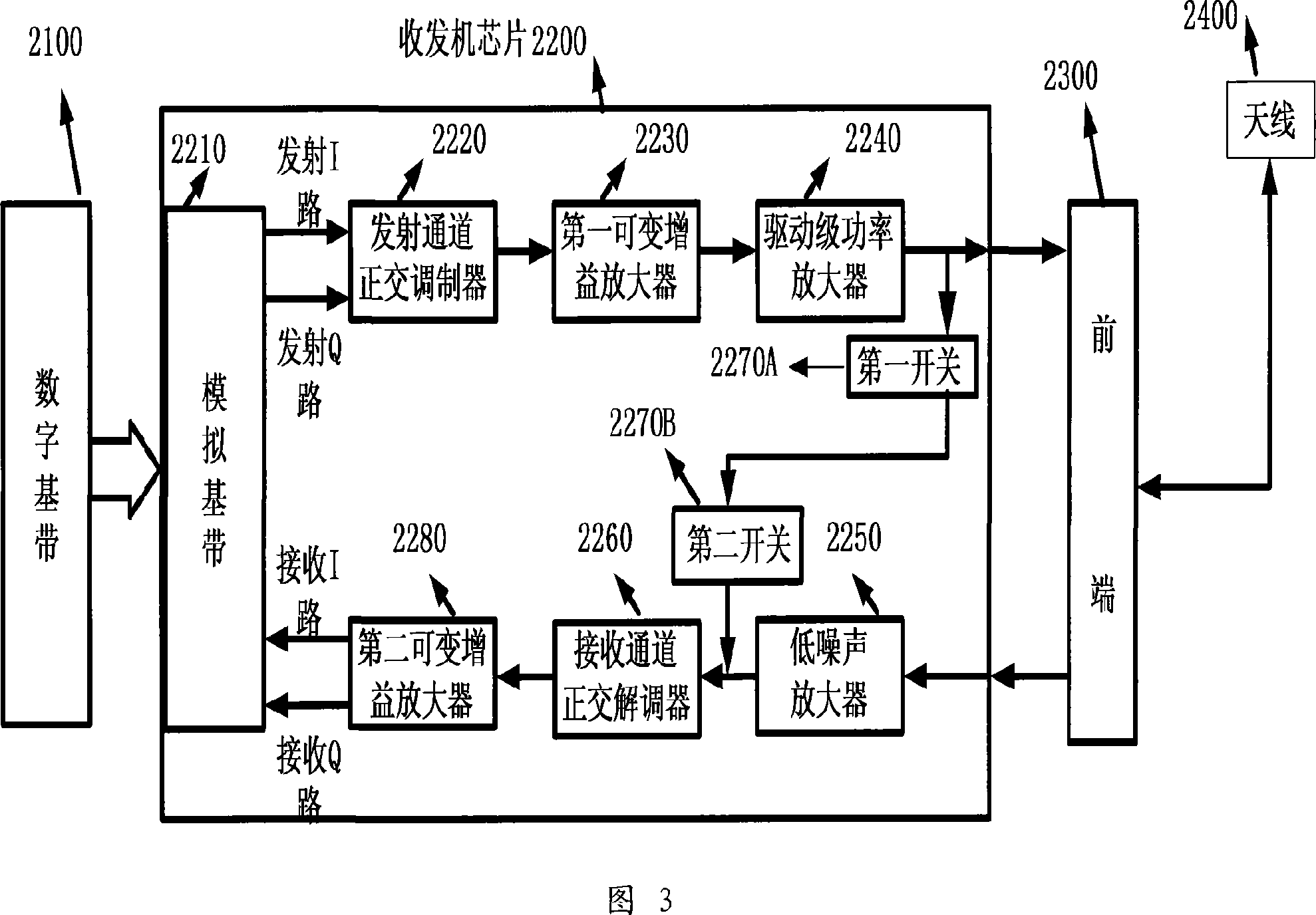
[0024] Fig. 3 is a system block diagram of the present invention. As shown in Figure 3, 2100 is a digital baseband for information processing; 2300 is a front end, including switches, filters, power ampl...


PUM


Abstract

The method includes following steps: (1) DC offset correction for the receiving channel to obtain value of residual error; (2) switching on the transmitting channel and the receiving channel, and obtaining configured gain reasonably; (3) carrying out calibration for carrier wave leakage (CWL) power to calculate out compensation value; (4) turning off the receiving channel, and in transmission procedure, compensation value are carried in sub circuits in the transmitting channel in order to complete CWL and compensation. The invention also discloses device for restraining CWL. Structure of the device includes at least digital baseband, chip of transceiver, front end, and antenna. Without need of additional directional coupler and power detection apparatus, the invention through the receiving channel detects CWL power existed in the transmitting channel. The invention does not need multiple iterations to solve and search optimal value. The compensation algorithm is high performance.

Description

technical field [0001] The invention relates to the technology in the field of wireless communication, and specifically relates to a method and device for suppressing carrier leakage in a radio frequency chip transceiver architecture. Background technique [0002] In today's RF transceiver systems, carrier leakage into the transmitter output port causing interference is common. Carrier leakage is generally caused by the unsatisfactory device or process itself, such as the limited isolation between the RF port of the mixer and the local oscillator port, and the mismatch degree of the device under the process. The local oscillator has a high-frequency source during frequency conversion. The high frequency source leaks through the antenna and mixes with the useful signal to cause carrier leakage. Carrier leakage is not a useful signal, it becomes interference when it leaks to the transmitter port. [0003] At present, in order to effectively suppress carrier leakage, there a...

Claims


Application Information

Patent Timeline
Patent Type & Authority Applications(China)
IPC IPC(8): H04B1/40H04B1/48H04B1/10
Inventor 王险峰赵林新朱立振
Owner SPREADTRUM COMM (SHANGHAI) CO LTD
Why Eureka
Try Eureka