
Detection system for detecting translations of a body

A technology of objects and detectors, which is applied in the field of translation systems, can solve problems such as the inability to measure the out-of-plane translation of the substrate, and achieve high-precision results

Inactive Publication Date: 2007-10-24
KONINKLIJKE PHILIPS ELECTRONICS NV
View PDF1 Cites 0 Cited by
  • Summary
  • Abstract
  • Description
  • Claims
  • Application Information

AI Technical Summary

Problems solved by technology

But the probing device cannot measure the out-of-plane translation of the substrate

Method used


Image

  • Detection system for detecting translations of a body
  • Detection system for detecting translations of a body
  • Detection system for detecting translations of a body

Examples


Embodiment Construction

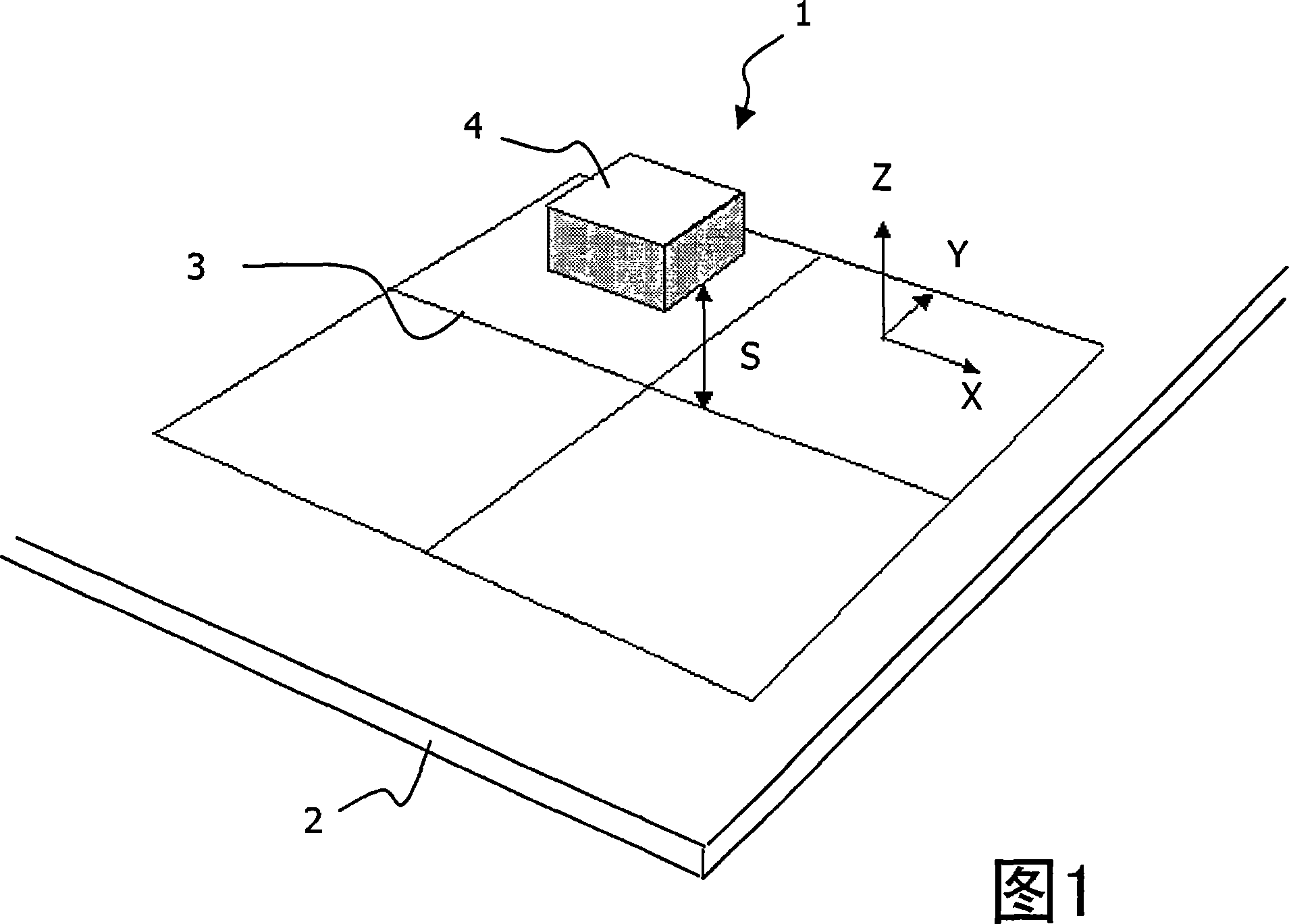
[0043] Fig. 1 schematically shows a system 1 for detecting a translation of an object 2 with a diffractive pattern 3 applied to it, hereinafter also referred to as a grating 3 . For example, the object may be a wafer or a printed circuit board. The diffractive pattern 3 may be applied directly to the object 2, or it may be attached to the object 2 via one or more intermediate or auxiliary components (not shown). The measuring heads 4 are arranged at a distance S to detect translations of the object 2 in the indicated X, Y, Z directions.

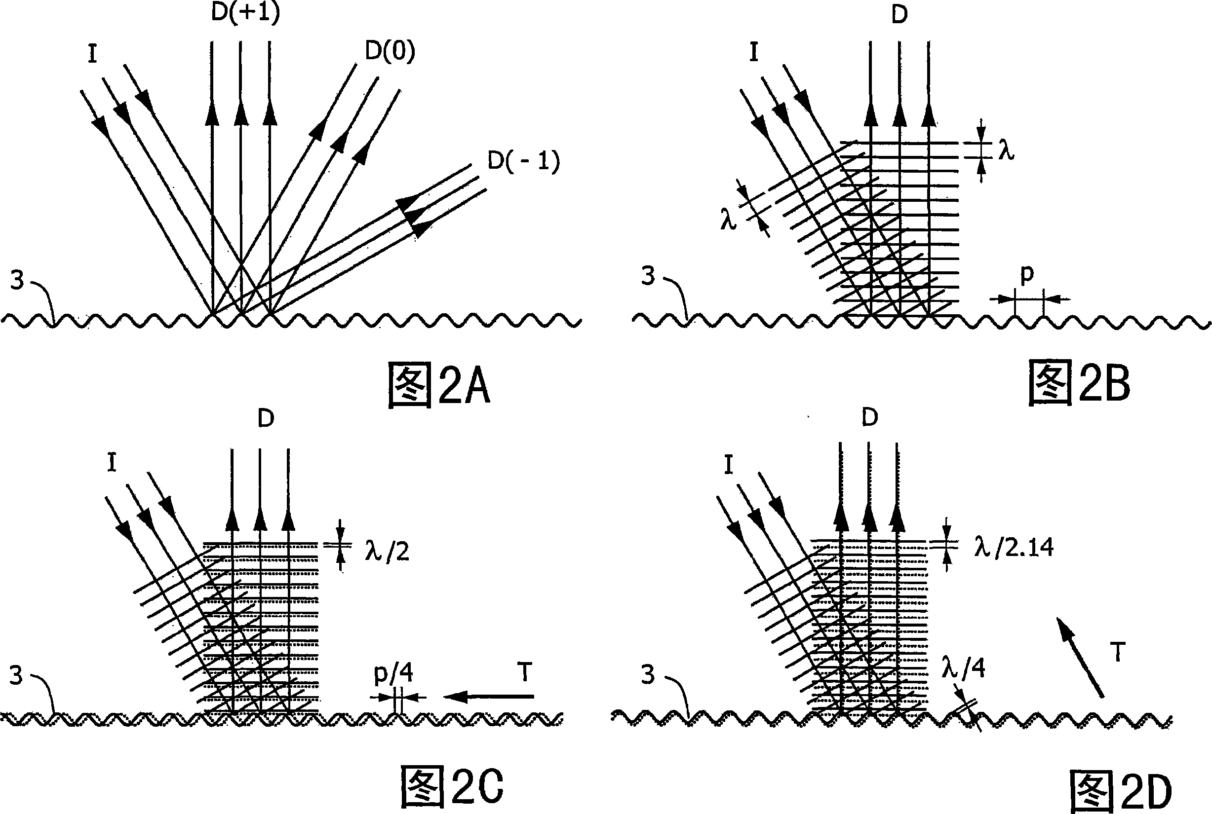
[0044]2A-2D show schematic diagrams of the translation effect of the periodic reflection grating 3 . In FIG. 2A , an incident light beam I is directed towards a grating 3 . The incident beam I is diffracted from the grating at rest to form a diffracted beam D. The figure shows the diffraction orders D(-1), D(0) and D(+1) of the diffracted beam. FIG. 2B shows the first stage in the same state, where the wavelengths λ of the incident beam ...


PUM


Abstract

The invention relates to a system (1) for detecting a translation (T) of a body (2) with a diffraction pattern (3) applied to said body. The system comprises means (4) for providing an incident light beam (I) to said diffraction pattern and to obtain a diffracted light beam (D) from said diffraction pattern; means (4) for measuring a phase difference by interference between said incident light beam and said diffracted beam an means (4) for detecting said translation on the basis of said measured phase difference. The invention further relates to a method for detecting a translation of a body (2); a redirection arrangement 6 and a frequency multiplexing system.

Description

technical field [0001] The invention relates to a system for detecting translation of an object. More specifically, the present invention relates to systems for detecting translation of an object bearing a diffractive pattern by providing incident light thereto, in particular said translation being parallel to the normal to the plane bearing said diffractive pattern . The invention also relates to a method, a redirection device and a frequency multiplexing system for detecting the translation of an object with a diffractive pattern. Background technique [0002] Precise measurement of the position or change in position of moving objects is required in various technical applications. For example, lithographic projection tools and wafer inspection tools employed in the semiconductor industry require accurate information about changes in the position of the semiconductor wafer. Another field of application relates to the printed circuit board (PCB) industry, where informatio...

Claims


Application Information

Patent Timeline
Patent Type & Authority Applications(China)
IPC IPC(8): G01D5/38
CPCG01D5/38
Inventor 雷纳图斯·G.·克拉韦尔约翰·C.·康普特皮特·范德梅尔
Owner KONINKLIJKE PHILIPS ELECTRONICS NV
Learn More