
Electronic product with casing mounting-dismounting structure

A technology for electronic products and casings, applied in the field of electronic products, can solve the problems of increasing the number of parts, time-consuming and laborious, etc.

Active Publication Date: 2007-08-29
ASUSTEK COMPUTER INC
View PDF0 Cites 0 Cited by
  • Summary
  • Abstract
  • Description
  • Claims
  • Application Information

AI Technical Summary

Problems solved by technology

[0004] However, when assembling the casing of the traditional computer mainframe, a plurality of screws are used to screw the casing to the mainframe of the computer in a screw-locking manner. In this way, the user or maintenance personnel must use a screwdriver, which is time-consuming and laborious. and the number of parts will also increase
[0005] Recently, some screws have been changed to thumb screws (manual screws). The principle is to lock the case on the body of the main computer in the same way as the screw lock. The only difference is that the user or maintenance personnel do not need to use a screwdriver. 1. The purpose of disassembly and assembly can be achieved only by using the hands of the human body. However, the thumb screw also needs to be rotated continuously to achieve the purpose of screw locking. This will also cause time-consuming and labor-intensive problems, which is not very ideal.

Method used


Image

  • Electronic product with casing mounting-dismounting structure
  • Electronic product with casing mounting-dismounting structure
  • Electronic product with casing mounting-dismounting structure

Examples


Embodiment Construction

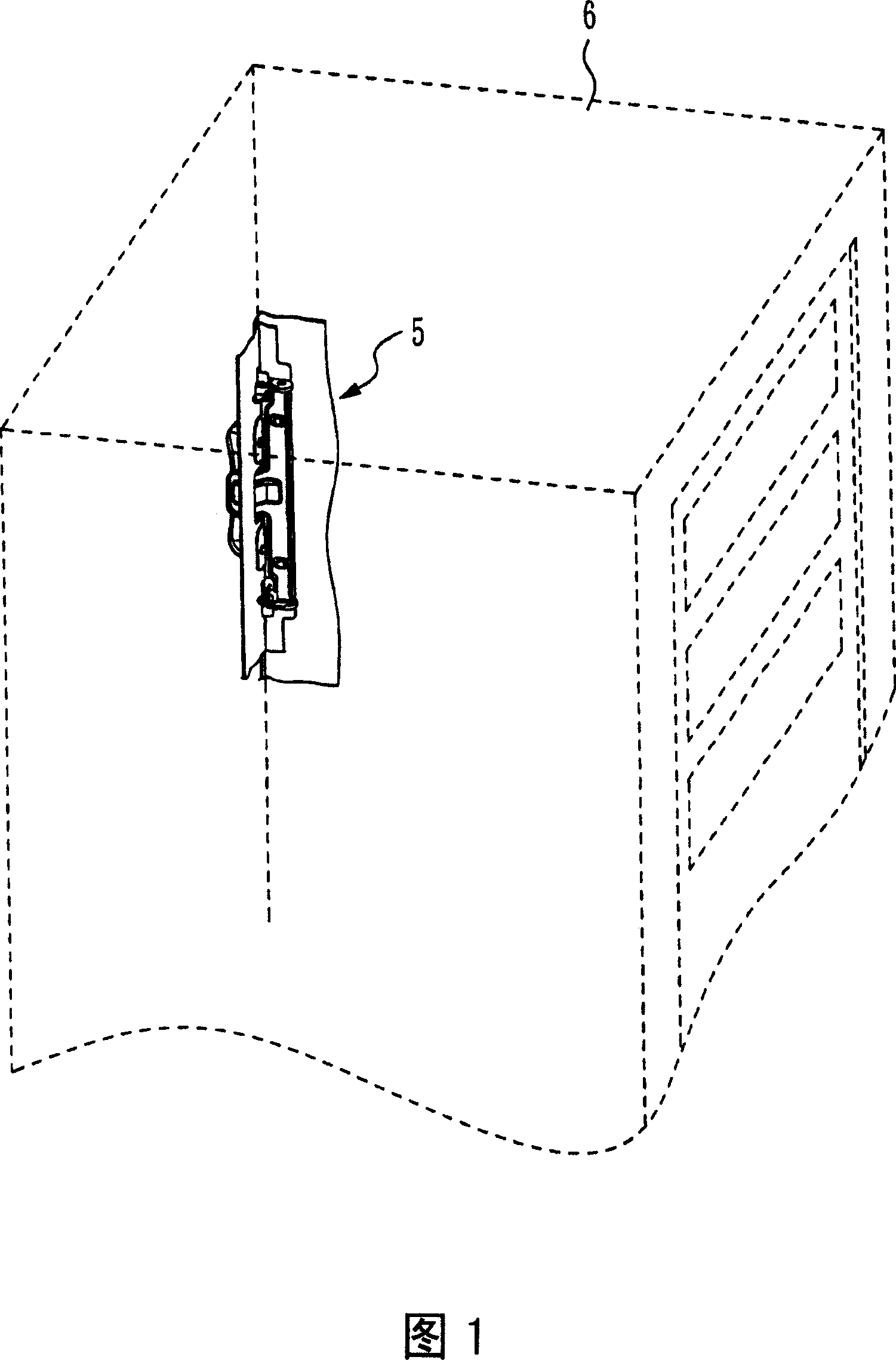
[0027] Please refer to FIG. 1 , which is a schematic diagram of the use state of the first preferred embodiment of the present invention, which is an electronic product of a computer host 6 assembled with a casing disassembly structure 5 of the present invention.

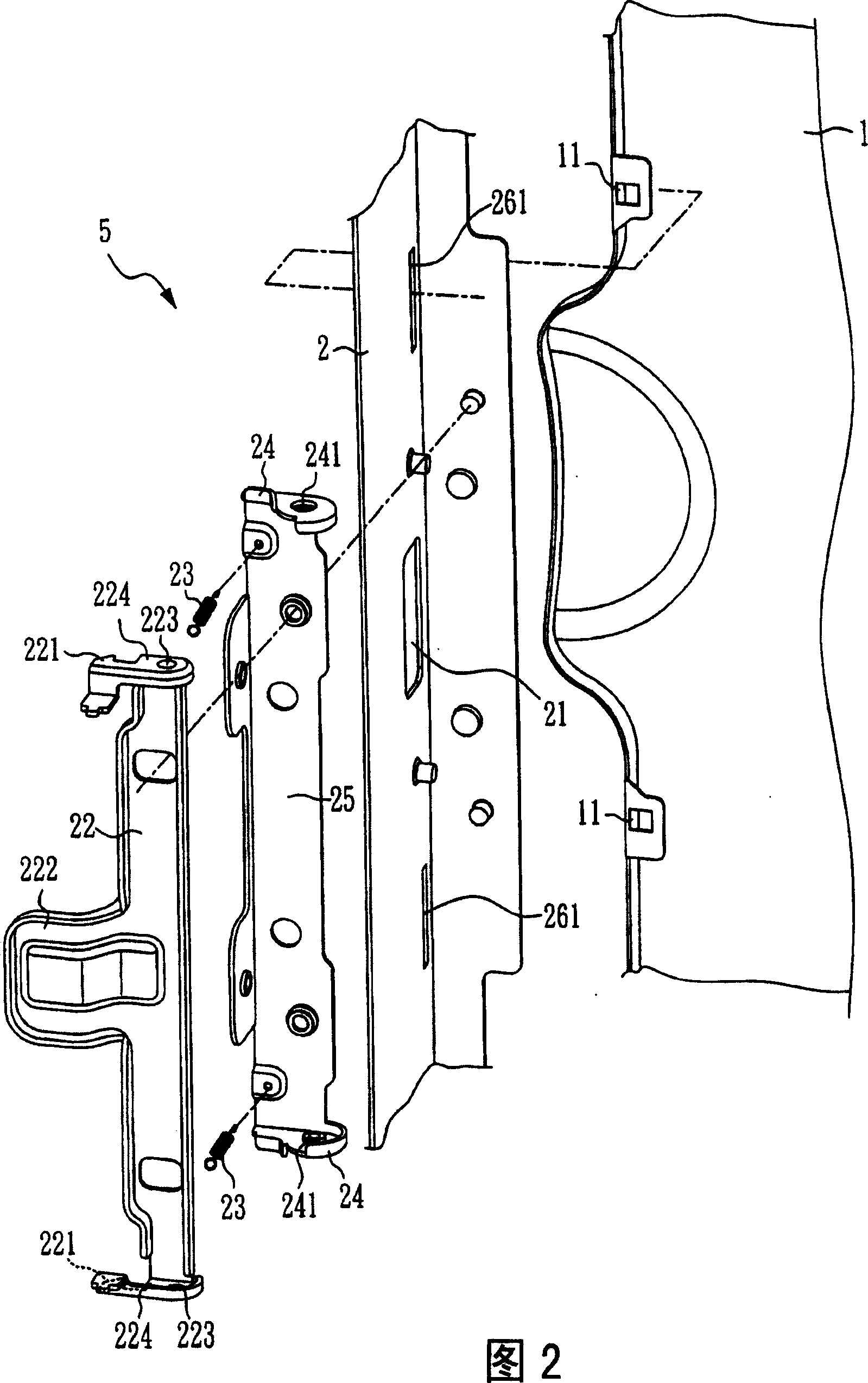
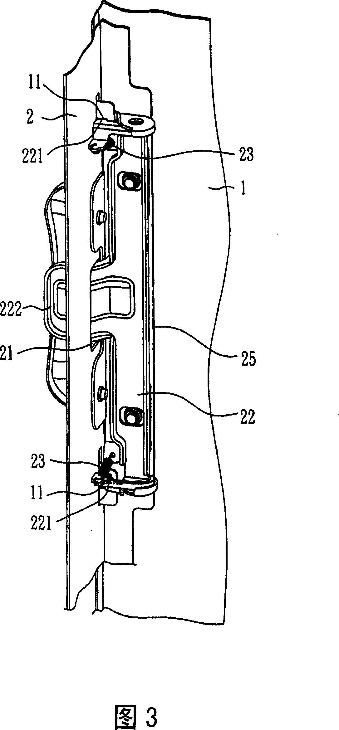
[0028] Please also refer to FIG. 2 which is an exploded view of the first preferred embodiment of the present invention, and FIG. 3 is an assembled view of the first preferred embodiment of the present invention, which shows that the above-mentioned casing disassembly structure 5 includes a first casing 1, and a second casing 2, and the first casing 1 includes two first engaging portions 11, in this embodiment, the two first engaging portions 11 are respectively a first opening, and They are respectively located on two sides of the first casing 1 .

[0029] In addition, the second casing 2 of the casing dismounting structure 5 in the drawing is adjacent to the first casing 1, and the second casing 2 includes a rotat...


PUM


Abstract

Second chassis is abutted to first chassis. Being pivot located in second chassis, a revolving part of second chassis rotates between first position and second position. When the revolving part is positioned at second location, a piece of elastic module of the second chassis provides a pulling force to prompt the revolving part to rotate forwards to first location. When the revolving part is located at first location, second clip part of the second chassis is clipped into first clip part of the first chassis. When the revolving part is located at second location, second clip part of the second chassis is disengaged from first clip part. Using simple combined reassembling structure, the invention reaches purpose of reassembling between chassis. Advantages are: saving time and saving manpower, and reducing number of parts.

Description

technical field [0001] The present invention relates to an electronic product, in particular to an electronic product suitable for a disassembly and assembly structure of a casing, such as a computer mainframe and the like. Background technique [0002] For general electronic products, when repairing or assembling the internal components of the electronic product, the user or maintenance personnel must disassemble the casing of the electronic product before performing maintenance or assembling operations. [0003] Taking the computer mainframe as an example, when the user or maintenance personnel is repairing or assembling the internal components of the computer, for example, when repairing or assembling the central processing unit (CPU) on the computer motherboard, the user or maintenance personnel must replace one of the computer mainframe components. Or multiple casings are disassembled, and the casings are assembled after the internal components of the computer are repai...

Claims


Application Information

Patent Timeline
Patent Type & Authority Applications(China)
IPC IPC(8): H05K5/00H05K7/00
Inventor 江林旭李冠延
Owner ASUSTEK COMPUTER INC
Learn More