
Cutter, cutter head disc, cutter head and device thereof

A technology of cutter head disk and cutter head, which is applied in the direction of grain processing, etc., can solve the problem that the connection between the blade and the cutter head disk is not always safe.

Inactive Publication Date: 2009-07-08
CFS GERMANY
View PDF6 Cites 1 Cited by
  • Summary
  • Abstract
  • Description
  • Claims
  • Application Information

AI Technical Summary

Problems solved by technology

Besides that, in order to obtain a good cutting result and also for the sake of safety, it is important that the special blades are individually attached to the disc designed for them, which according to the prior art is not connected to the disc. always safe

Method used


Image

  • Cutter, cutter head disc, cutter head and device thereof
  • Cutter, cutter head disc, cutter head and device thereof
  • Cutter, cutter head disc, cutter head and device thereof

Examples


Embodiment Construction

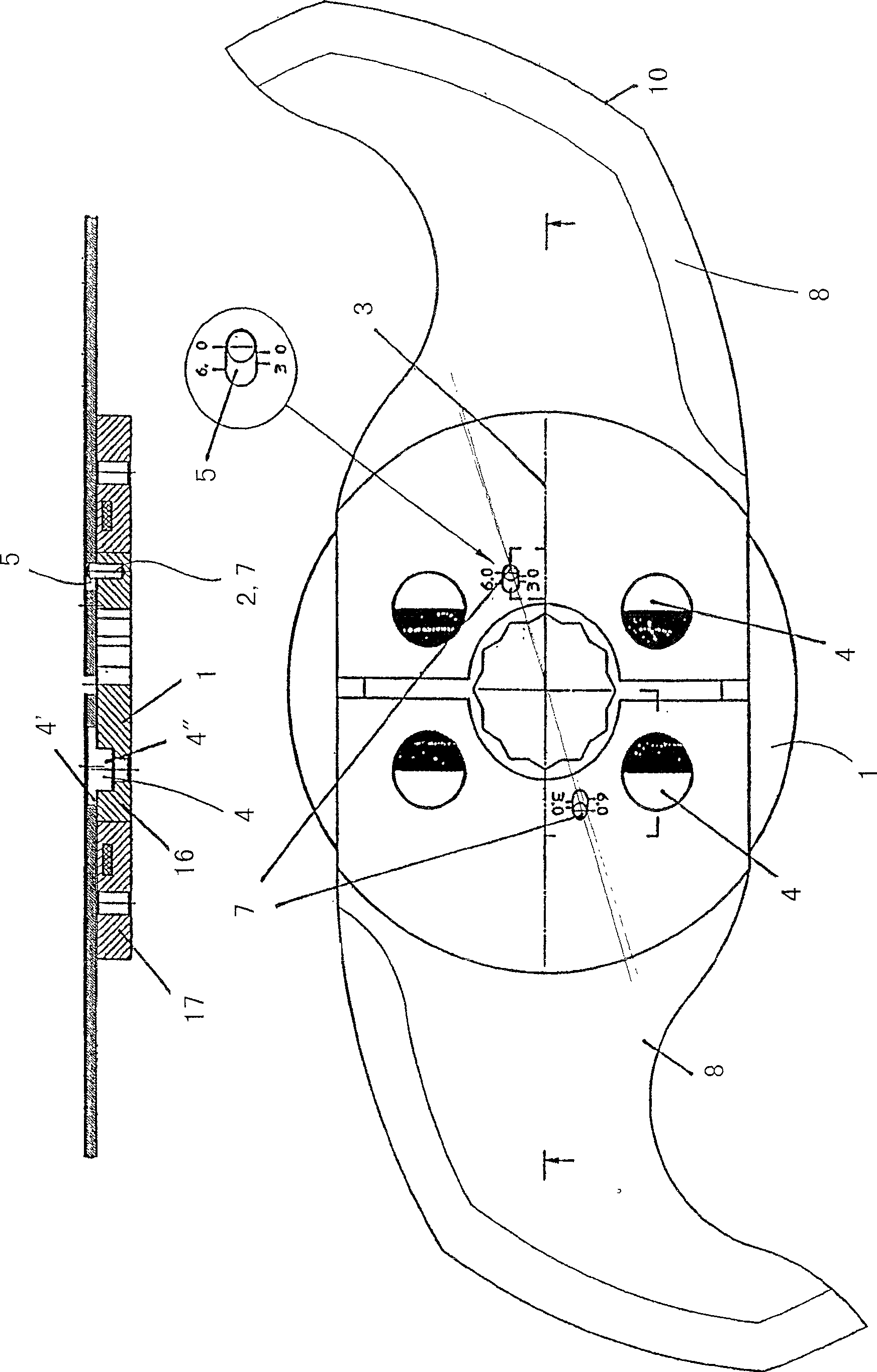
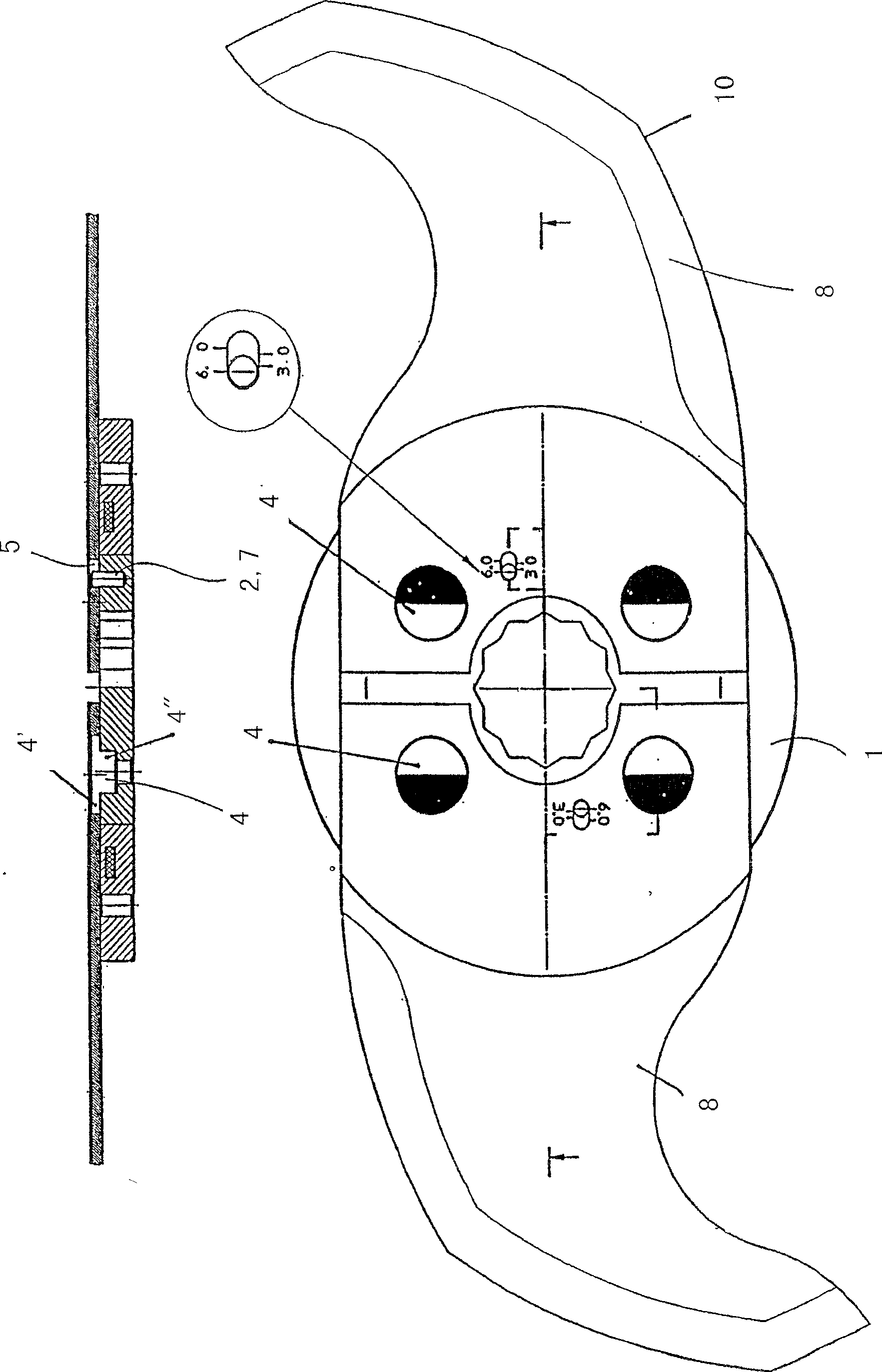
[0025] exist figure 1 Indicated by 8 is the blade of the invention, which rotates in a knife (not shown) in the direction indicated by the arrow represented by reference number 9 . The blade thus has a cutting edge 10 on its lower radius. The blades are positioned on the cutter head disc through two holes 4 . According to the invention, the blade has a longitudinal hole 5 arranged offset from the central axis of the blade 8 . Described longitudinal hole 5 has calibration, adopts calibration to be able to identify the position of described blade relative to described cutter head disk, will refer to figure 2 and image 3 This is explained in more detail.

[0026] figure 2 Two blades 8 arranged on the cutter head disc 1 are shown. The cutter head disc 1 has four cutouts or holes, each of them for an eccentric retaining pin 4, by means of which the blade 8 is positioned in the cutter head disc 1 . The eccentric retaining pin 4 has a disk-shaped head 4 which is arranged e...


PUM


Abstract

The invention relates to a cutter knife (8), a cutter head disk (1) and a system including the inventive cutter head disk and the inventive knife, wherein the cutter knife includes a longitudinal bore enabling only one cutter knife to be arranged on the cutter head disk, the longitudinal bore thereof being compatible with the pin. The scaling on the longitudinal bore makes it possible to verify the position of the cutter knife in relation to the cutter head disk.

Description

technical field [0001] The invention relates to a cutter, a cutter head disc and a cutter head, the cutter head comprising the cutter head disc of the invention and the blade of the invention. Background technique [0002] Knives for comminution and mixing of fresh or frozen foods such as meat have a cutter head consisting of a plurality of blades arranged in succession fastened to a part called a cutter head disc. The blades must be arranged in a very specific configuration in order to obtain a satisfactory cutting result. Besides that, in order to obtain a good cutting result and also for safety reasons, it is important that the special blades are individually attached to the discs designed for them, which according to the prior art are not connected to the discs. Always safe. Contents of the invention [0003] It is therefore an object of the present invention to provide a knife which avoids the disadvantages of the prior art. [0004] According to the invention, the...

Claims


Application Information

Patent Timeline
Patent Type & Authority Patents(China)
IPC IPC(8): B02C18/18B02C18/06B02C18/20
CPCB02C18/20B02C18/065Y10T83/501Y10T83/866
Inventor N·亚科比J·伯恩哈德特
Owner CFS GERMANY
Learn More