
Knee prosthesis with rotation bearing

a technology of rotation bearing and knee prosthesis, which is applied in the field of knee prosthesis with rotation bearing, can solve the problems of large practical difficulties, limited degree of freedom of prosthesis, and relatively high cost of using a prosthesis

Active Publication Date: 2009-09-22
WALDEMAR LINK GMBH & CO
View PDF17 Cites 16 Cited by
  • Summary
  • Abstract
  • Description
  • Claims
  • Application Information

AI Technical Summary

Benefits of technology

[0002]Nevertheless, in endeavouring to make available a prosthesis which permits a simple intraoperative decision between the rotation-free and the rotationally fixed version, the invention follows on from the latter proposal and makes it suitable in practical terms by means of the features of the invention of this application. Accordingly, the intermediate part which connects the femoral component to the tibial component, and forms the rotation bearing with the tibial component, is provided with a projection which engages in a matching recess in the tibial component.

Problems solved by technology

If this ability too has been lost, the rotation movement must be excluded and the degree of freedom of the prosthesis must be limited to the flexion movement.
In fact, there are a great many practical difficulties against it.
One factor may have been that, compared to a prosthesis which exclusively includes a flexion hinge, it is relatively expensive to use a prosthesis additionally provided with a rotation bearing and then to lock this.

Method used


Image

  • Knee prosthesis with rotation bearing
  • Knee prosthesis with rotation bearing
  • Knee prosthesis with rotation bearing

Examples


Embodiment Construction

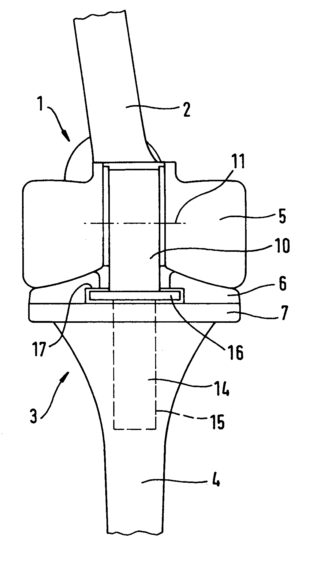
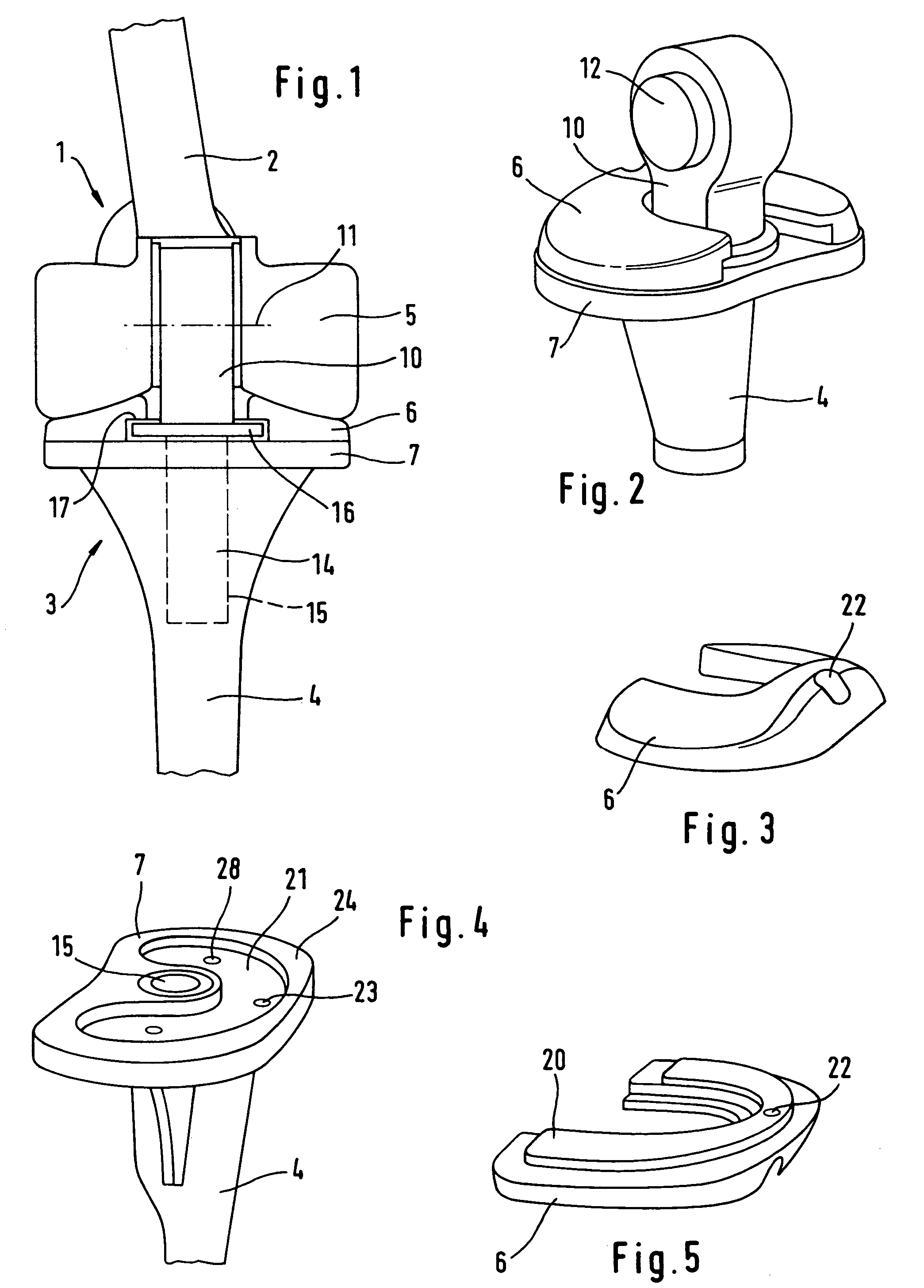
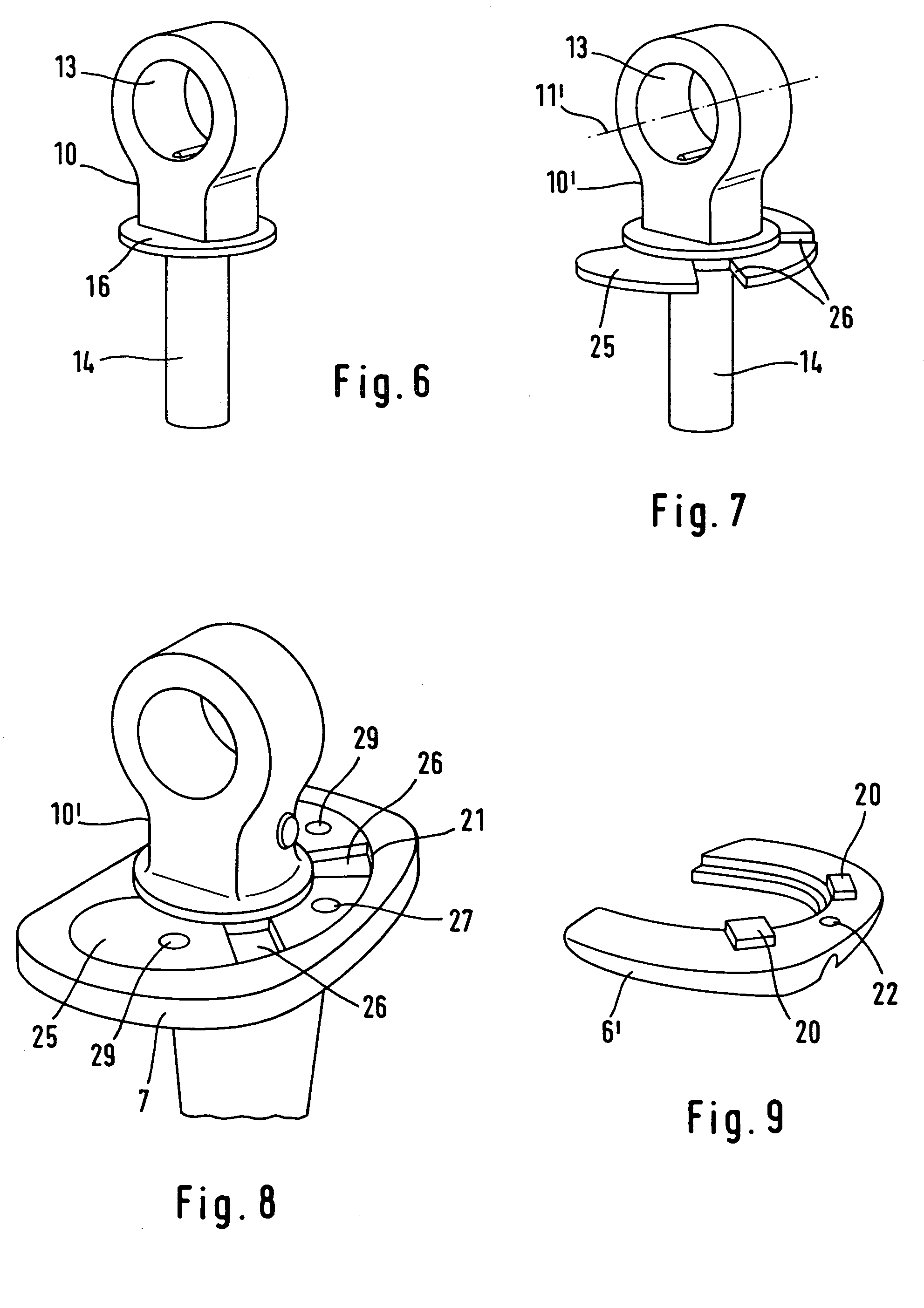
[0015]The prosthesis has a femoral component 1 with a stem 2 intended for implantation in the femoral bone, and a tibial component with a stem 4 intended for implantation in the tibia. The femoral component has wing-like runners 5 lying on a tibial plateau 6 which promotes sliding and which is supported by a support plate 7 of the tibial component. To stabilize the two components relative to one another, an intermediate piece 10 is provided which, with the femoral component, forms a hinge indicated in FIG. 1 by an axis line 11. FIG. 2 shows an axis stump 12 which protrudes from the intermediate piece 10 and which cooperates with bearing bores (not shown) in the femoral component 1. It sits in a bore 13 of the intermediate part.

[0016]The intermediate piece 10 further forms a rotation bearing with the tibial component, namely by the rod 14 which is connected integrally to the intermediate part and which is mounted in a bearing bore 15 in the tibial component. The bearing bore 15 exten...


PUM


Abstract

A knee prosthesis including a femoral component, a tibial component and an intermediate piece which connects these forming a flexion bearing with the femoral component and a rotation bearing with the tibial component, which rotation bearing can be locked relative to the tibial part. To allow the physician to decide during the operation whether to use a rotation-free prosthesis or a rotationally fixed prosthesis, the intermediate piece is alternatively provided with a projection which engages in a matching recess in the tibial component.

Description

FIELD AND BACKGROUND OF THE INVENTION[0001]The poorer the state of preservation of the ligament apparatus of a knee which is to be provided with a knee prosthesis, the greater inherent stability demanded of the prosthesis. If it is a ligament apparatus of reduced stability, it may be necessary to use a prosthesis type in which the relative movement between femoral component and tibial component is limited by a stabilizing intermediate part to the flexion movement about a horizontal transverse axis and to a rotation movement about an axis substantially parallel to the tibia (DE-C-2 744 710). For this, it is required that the ligament apparatus can at least still control the rotation movements. If this ability too has been lost, the rotation movement must be excluded and the degree of freedom of the prosthesis must be limited to the flexion movement. Different prosthesis structures are normally used for these two cases of application. If the decision whether to choose a rotation-free ...

Claims


Application Information

Patent Timeline
Patent Type & Authority Patents(United States)
IPC IPC(8): A61F2/38A61F2/00A61F2/30
CPCA61F2/385A61F2/3868A61F2250/0062A61F2/389A61F2002/30131A61F2002/30367A61F2002/30507A61F2002/30574A61F2002/30604A61F2002/30607A61F2002/30797A61F2002/30878A61F2002/30884A61F2220/0025A61F2220/0033A61F2230/0013A61F2/3859A61F2/38
Inventor KELLER, ARNOLD
Owner WALDEMAR LINK GMBH & CO
Learn More