
Seismic sensors

a technology of seismic sensors and sensors, applied in the field of seismic exploration, can solve the problems of increasing the difficulty of achieving, the spring cannot compensate for the weight of the coil in all directions, and the geophones provide no useful information, etc., and achieve the effect of meliorating or eliminating the gravity

Inactive Publication Date: 2007-11-06
SERCEL AUSTRALIA
View PDF11 Cites 19 Cited by
  • Summary
  • Abstract
  • Description
  • Claims
  • Application Information

AI Technical Summary

Benefits of technology

[0009]Accordingly, the preferred embodiment of the invention provides a method for compensating for the effect of gravity on seismic sensors and thus an improved sensor assembly which:
[0011](ii) can be deployed without having to mechanically control the tilt of the sensor;
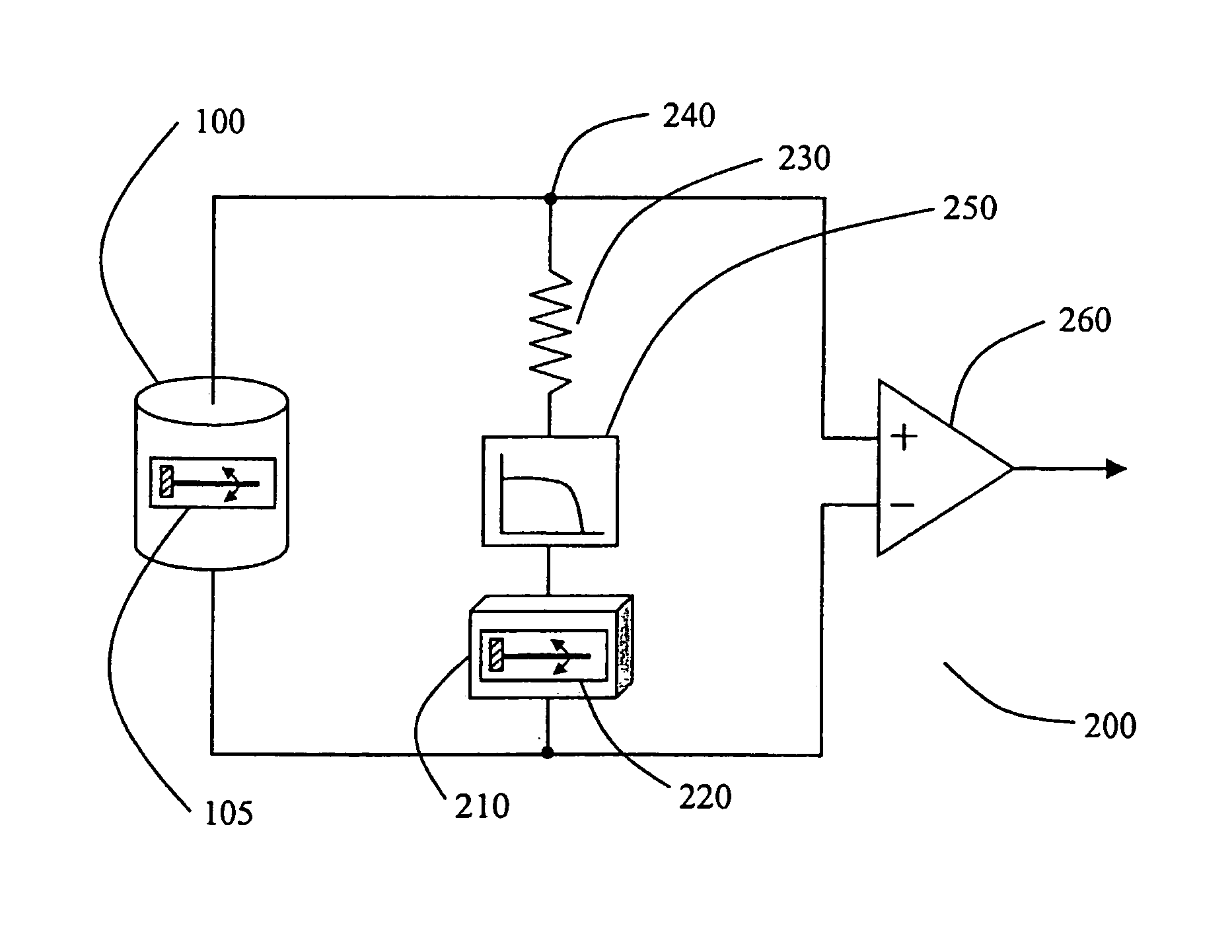
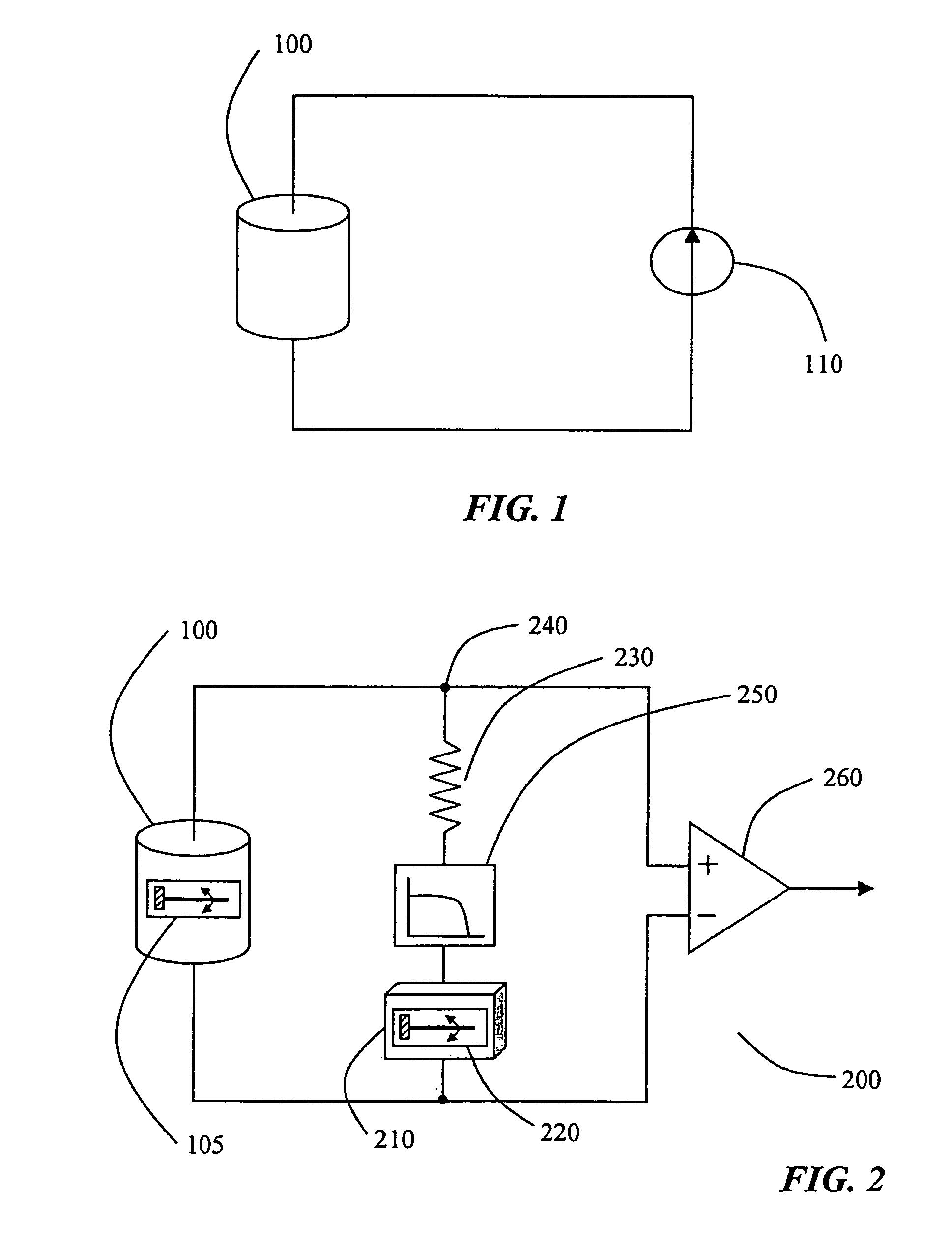
[0018]a current generator including a filter for determining a DC voltage in response to said tilt signal so as to provide a current to said coil to induce a force on the coil that at least partially compensates for a weight of the coil, thereby ameliorating or eliminating a gravitational effect on said primary sensor.
[0022]a current generator responsive to said tilt signal so as to provide a current to said coil to induce a force on the coil that at least partially compensates for a weight of the coil, thereby ameliorating or eliminating a gravitational effect on said geophone,
[0027]using an accelerometer having a second axis of sensitivity parallel to said first axis of sensitivity, said accelerometer being in combination with a law pass filter to generate an external bias current within said coil to induce a force on the coil that at least partially compensates for a weight of said coil, thereby ameliorating or eliminating a gravity effect on said seismic sensor.

Problems solved by technology

A lower resonance frequency is generally desirable, but is more difficult to achieve.
Due to stroke limitations, the spring cannot compensate for the weight of the coil for all directions.
Such geophones typically maintain their performance specifications within a range of 20 degrees of tilt, beyond which the geophones provide no useful information.
This last point is a very significant drawback when three axis systems are to be used since it degrades “vector fidelity”.
It is also a problem when geophones are combined with hydrophones as is often the case in ocean bottom operations.
Gimbals usually introduce parasitic resonances that have to be damped using viscous damping liquids which can negatively impact on the operation of the sensors.
Some solutions have been proposed to lock the gimbals after deployment, like the one disclosed in U.S. Pat. No. 6,061,302, but the end result is a complex and expensive mechanical system.
Some Micro-machined Electro Mechanical Systems (MEMS) type of accelerometers have been recently developed for such an application, like the one disclosed in Vectorseis Pat. No. WO055646A1, but their cost is much higher than the cost of traditional geophones due to the additional complexity.

Method used


Image

  • Seismic sensors
  • Seismic sensors
  • Seismic sensors

Examples


Embodiment Construction

[0032]Some sample embodiments of the present invention will now be described in greater detail. Nevertheless, it should be recognized that the present invention can be practiced in a wide range of other embodiments besides those explicitly described, and the scope of the present invention is expressly not limited except as specified in the accompanying claims.

[0033]Moreover, while the present invention is illustrated by a number of preferred embodiments directed to ocean bottom systems, it is not intended that these illustrations be a limitation on the scope or applicability of the present invention. Apart from ocean bottom systems, the present invention is also applicable other applications such as both land and shallow water operations as well as to seismic streamers. Further, various parts of the present invention have not been drawn to scale. Certain dimensions have been exaggerated in relation to other dimensions in order to provide a clearer illustration and understanding of t...


PUM


Abstract

A method for compensating the effect of gravity on seismic sensors such as geophones and a gravity effect-free seismic sensor are disclosed. The gravity effect-free seismic sensor of the present invention includes primary sensor (100) operatively responsive to seismic movements and hence generating a seismic signal by having a coil placed in a magnetic field in a first axis of sensitivity (105); an auxiliary sensor (210) operatively responsive to a gravity field for generating a tilt signal, thus provide current to the coil of the primary sensor (100) to induce a force on the coil that at least partially compensates for a weight of the coil, thus ameliorating or eliminating a gravity effect on the primary sensor (100).

Description

FIELD OF THE INVENTION[0001]The present invention is directed, in general, to the field of seismic exploration and, more particularly, to seismic sensors such as geophone assemblies. It also relates to a method for at least partially compensating for the effect of gravity on seismic sensors.DESCRIPTION OF THE PRIOR ART[0002]In marine seismic exploration such as seismic geophysical surveys, a seismic signal is introduced into the earth by using a seismic source. The seismic signal propagates through the earth in the form of a spherical wave front. As the wave front impinges upon subsurface geologic formations, a portion of the wave front is reflected upwardly from formation interfaces back to the earth's surface. The reflected waves are recorded by a plurality of sensors and the recorded data is processed to obtain information about the earth's subsurface. In seismic exploration on land, shallow water and marsh lands, geophones are typically used as sensors.[0003]The basic principles...

Claims


Application Information

Patent Timeline
Patent Type & Authority Patents(United States)
IPC IPC(8): G01V1/18
CPCG01V1/181
Inventor LUC, FRANCOIS
Owner SERCEL AUSTRALIA
Learn More