
Mounting device for a wire harness shield

Inactive Publication Date: 2005-06-07
YAZAKI NORTH AMERICA
View PDF10 Cites 28 Cited by
  • Summary
  • Abstract
  • Description
  • Claims
  • Application Information

AI Technical Summary

Benefits of technology

[0007]Accordingly, it is an object of this invention to provide a reliable, reusable device for mounting a wire harness shield to a vehicle panel or engine part.
[0009]A further object of the invention is to design lock and bracket components of the device to be simple and inexpensive to manufacture.
[0012]The lock component receives the two bracket arms. The free ends of the arms act on the ramp surfaces to mechanically pivot the deflectable section outward from the box while the stem passes through the gap. When the protrusion is within the opening, the deflectable section snaps back and the ledges lodge beneath the undersides of the bracket arms. Manual force on the push element will flex the deflectable section outward again, separating the ledges from the bracket arm undersides and enabling removal of the lock component from the bracket component.

Problems solved by technology

These hazards could include moisture, grime and heat.
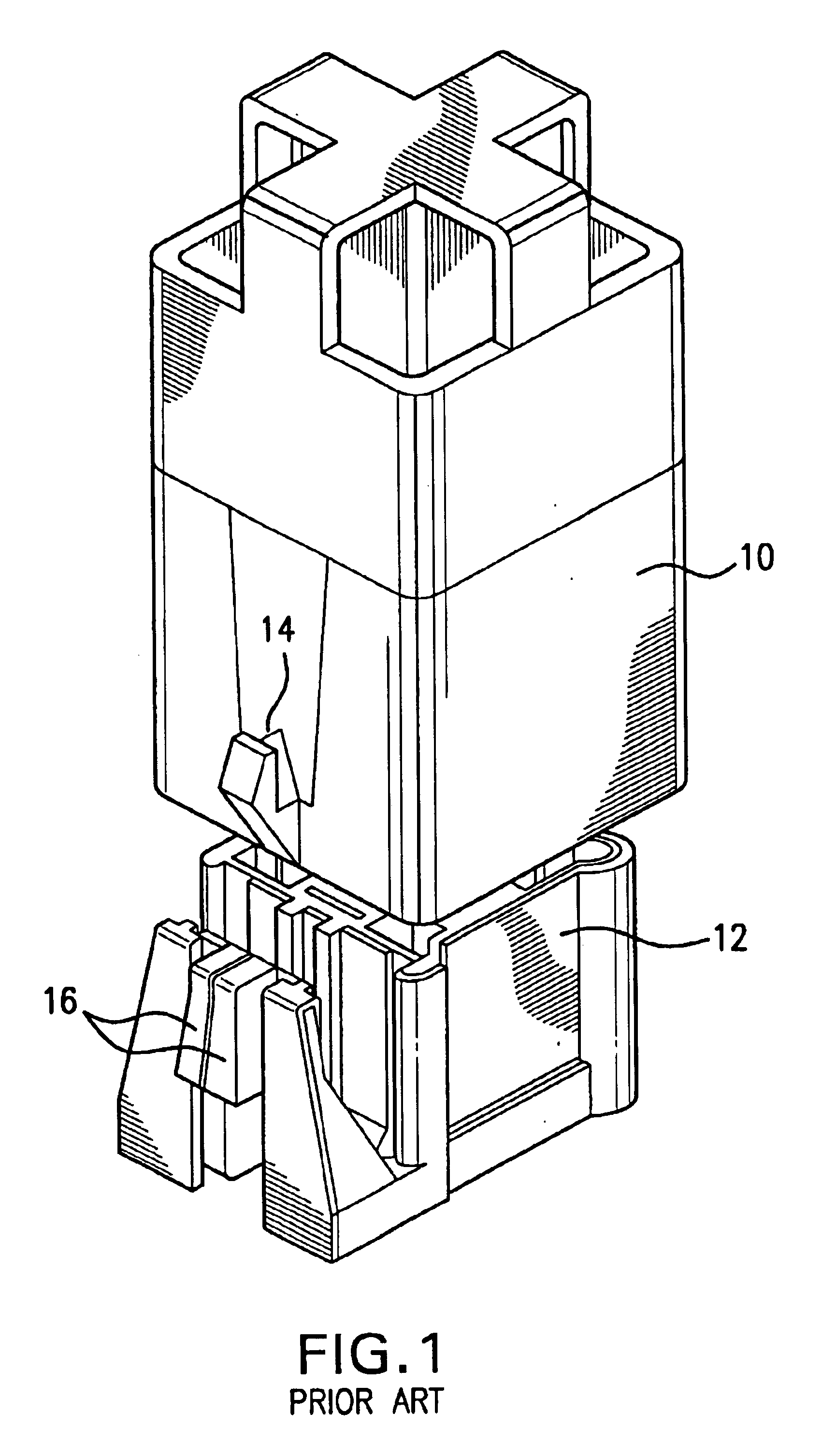
This becomes more time consuming and awkward to manage as longer wire harness covers require multiple locking structures.
The handle is also difficult to find since the mounting mechanism is located beneath the cover.
This particular locking structure doesn't work very well in practice, often requiring a lot of force to separate the lever split portions and two-handed operation to separate the shroud and connector.

Method used


Image

  • Mounting device for a wire harness shield
  • Mounting device for a wire harness shield
  • Mounting device for a wire harness shield

Examples


Embodiment Construction

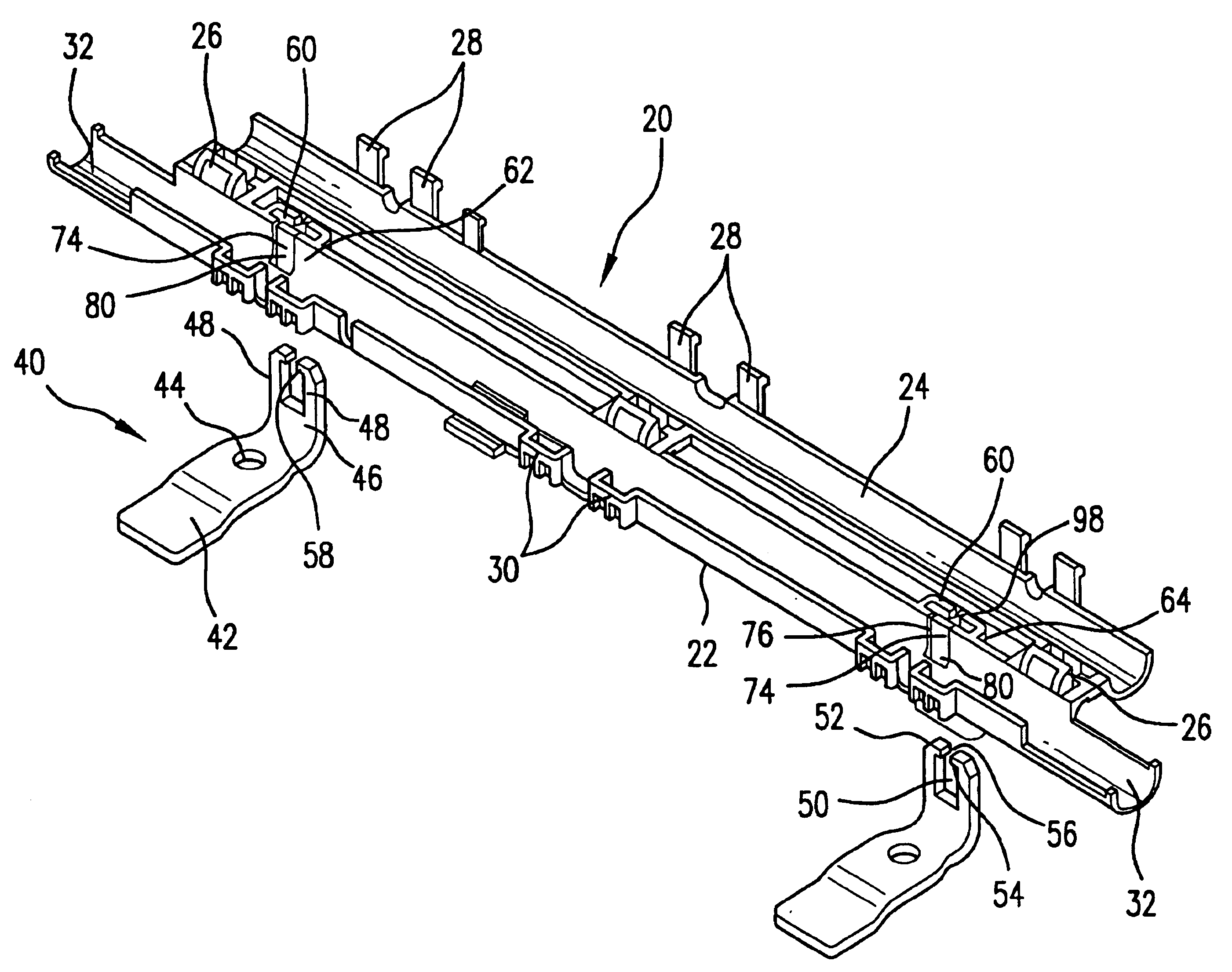
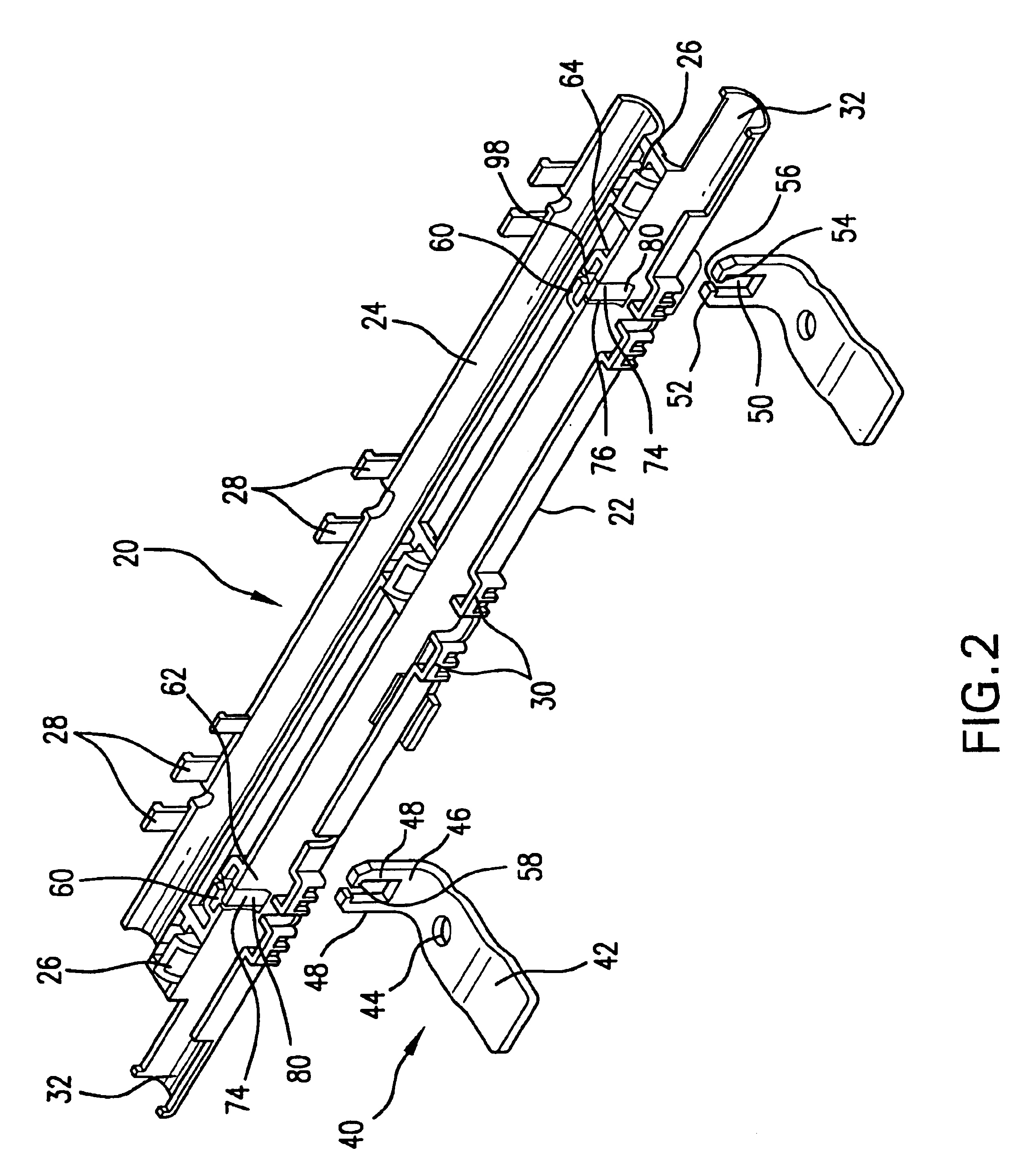
[0021]Referring now to FIG. 2, a wire harness shield 20 has a base 22 into which a wire harness can be laid. A lid 24 is attached to the base by hinges 26. Latch tabs 28 are received in complimentary locking frames 30 when the lid is pivoted to a closed position on the base, securing and protecting the harness in the shield. Fastening provisions 32 enable the harness to be taped to the shield to stabilize the assembly.

[0022]The shield 20 needs to be secured to an engine or vehicle part in the engine compartment, such as an intake manifold, fuel rail or body panel, to prevent damage to the harness. A mounting device according to the present invention comprises a first component in the form of a bracket 40. The bracket component, in FIG. 2, is illustrated as being L-shaped with an optional, long rectangular leg 42 having an aperture 44. A bolt, screw or other type of fastener can be inserted through the aperture 44 to attach the bracket to the engine part. A shorter leg 46 of the brac...


PUM


Abstract

A mounting device has a lock component attached to a wire harness shield and a bracket component for attachment to an engine part. The bracket component has two spaced, upright parallel arms defining an opening between them. The arms have free ends extending toward each other and separated by a gap. The lock component has a box-like shape with spaced sides. A deflectable section is formed in a first side. A stem extends from the deflectable section toward a second side of the lock component and through a slot in the second side. A push element is formed on an end of the stem extending from the slot. Latches or ledges are formed on ramp-shaped protrusions formed on the deflectable section on each side of the stem. When the lock component receives the parallel arms of the bracket component, the free ends of the arms act on the protrusions to force the deflectable section outward until the ledges snap beneath the free ends of the arms. To release the mounting device, pressing force on the push element moves the ledges from beneath the arms, and the lock component can be lifted from the bracket component.

Description

BACKGROUND OF THE INVENTION[0001]1. Field of the Invention[0002]The invention relates in general to the securing of wire harness shields and more specifically to a releasable device for reliably mounting a wire harness shield to an engine part in a vehicle.[0003]2. Discussion of Related Art[0004]Wire harness shields help maintain the dependability of the circuits and electrical connections within a wire harness. Providing a wire harness with a shield shelters the harness from environmental hazards within an engine compartment of a vehicle. These hazards could include moisture, grime and heat. Using the shield to secure a portion of the wire harness in a fixed position can safeguard the harness from damage caused by vehicle movement and vibration. The shields often need to be securely attached to a vehicle panel or engine part to furnish this protection.[0005]U.S. Pat. No. 5,597,980 discloses a mounting mechanism for securing a wire harness cover to a fuel injector rail. The mounting...

Claims


Application Information

Patent Timeline
IPC IPC(8): B60R16/02
CPCB60R16/0215Y10T403/606
Inventor JETTON, JAMES THOMAS
Owner YAZAKI NORTH AMERICA
Learn More