System and method for heavy equipment navigation and working edge positioning using an image acquisition device that provides distance information

a technology of distance information and image acquisition device, which is applied in the direction of vehicle position/course/altitude control, process and machine control, instruments, etc., can solve the problems of affecting the alignment and/or calibration of the delicate sensor mounted on the working edge, increasing the chance of damage, and affecting the accuracy of the positioning

Active Publication Date: 2014-09-18
HEXAGON TECH CENT GMBH
View PDF10 Cites 12 Cited by
  • Summary
  • Abstract
  • Description
  • Claims
  • Application Information

AI Technical Summary

Benefits of technology

The patent is about a new system that helps locate heavy equipment machines using a combination of GNSS and INS navigation systems. It uses a camera to capture images of a target attached to the machine, which are then converted into a coordinate system. This information is used to accurately control the machine's working edge, allowing for precise grading and other operations. The system overcomes previous limitations of GNSS and INS navigation by combining the two technologies to provide more accurate location information.

Problems solved by technology

One noted a disadvantage of conventional heavy equipment working edge control systems is that the delicate sensors are mounted on the working edge and are therefore subject to being damaged during normal operation of the machine.
This increased chance of damage is the result of being located in a very stressful work environment.
These stresses may be the result of dirt or other material striking the sensors, thereby damaging them or knocking them out of alignment and / or calibration.
The damage of sensors due to the stressful work environment in which they are located reduces the effectiveness of automatic working edge control systems.
Thus, the expected reduction of inefficiencies through the use of an automated working edge control system are lost due to the down time spent in repairing / replacing sensors.

Method used


Image

  • System and method for heavy equipment navigation and working edge positioning using an image acquisition device that provides distance information
  • System and method for heavy equipment navigation and working edge positioning using an image acquisition device that provides distance information
  • System and method for heavy equipment navigation and working edge positioning using an image acquisition device that provides distance information

Examples


Embodiment Construction

Heavy Equipment and Working Edges

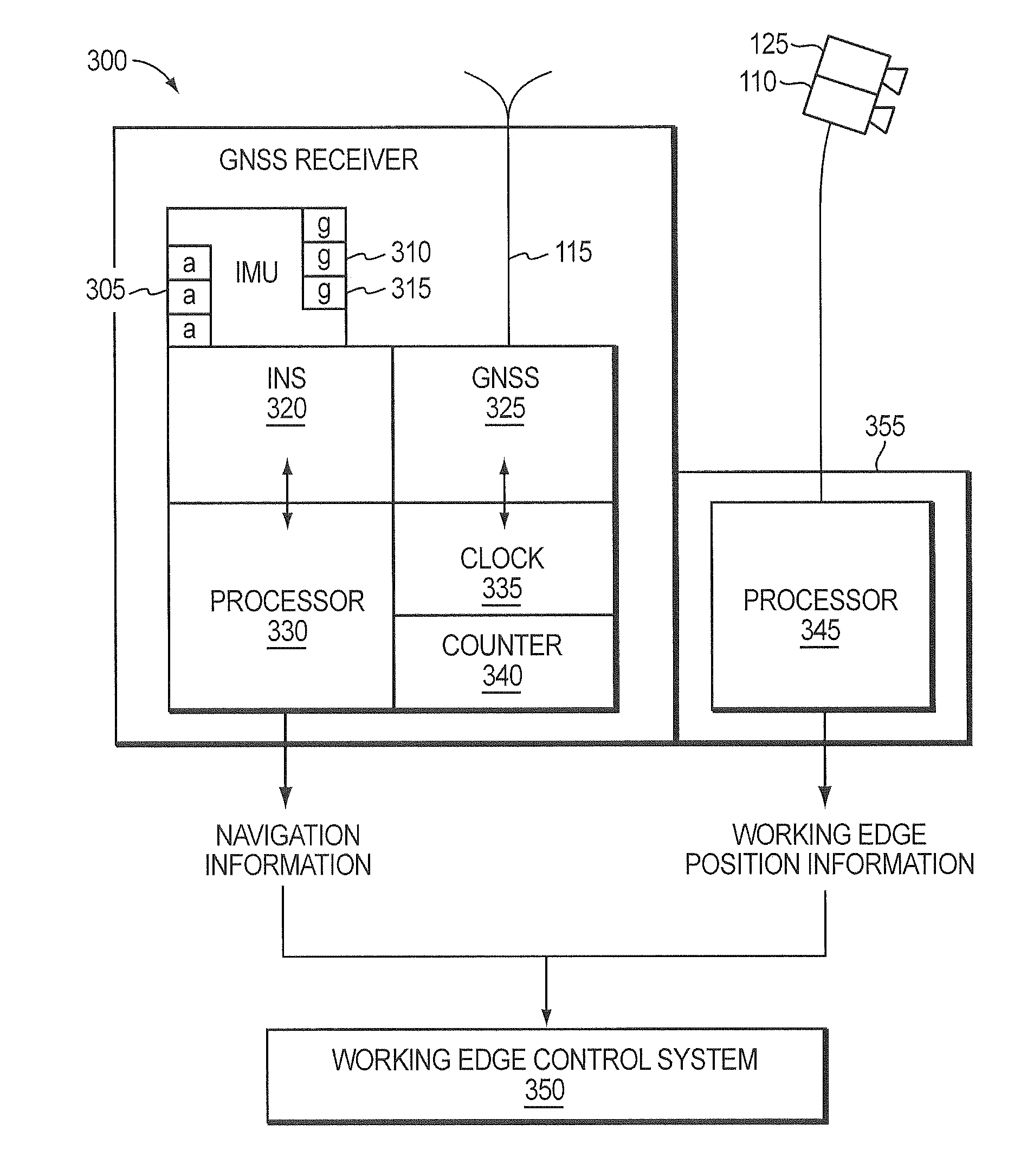
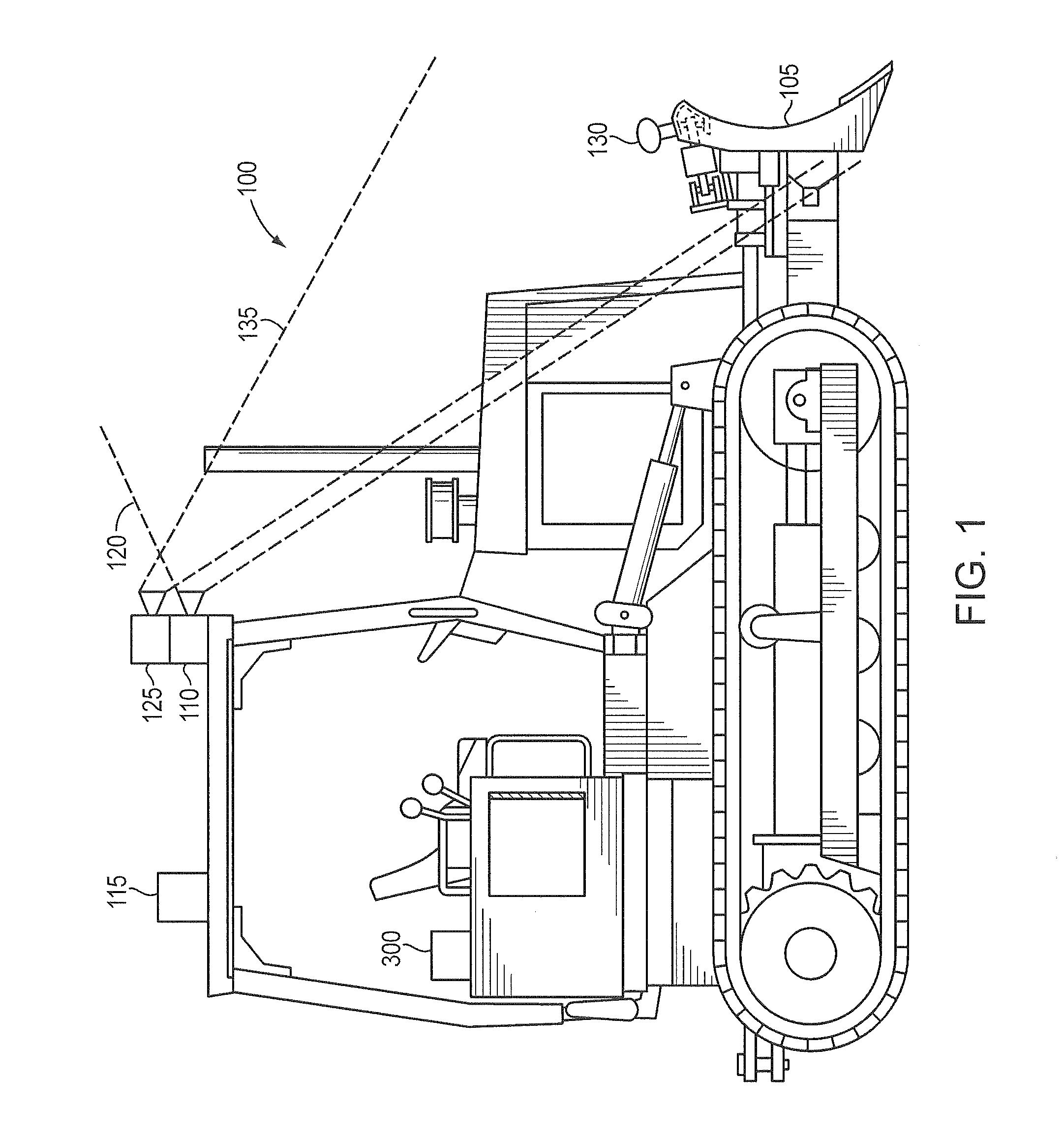
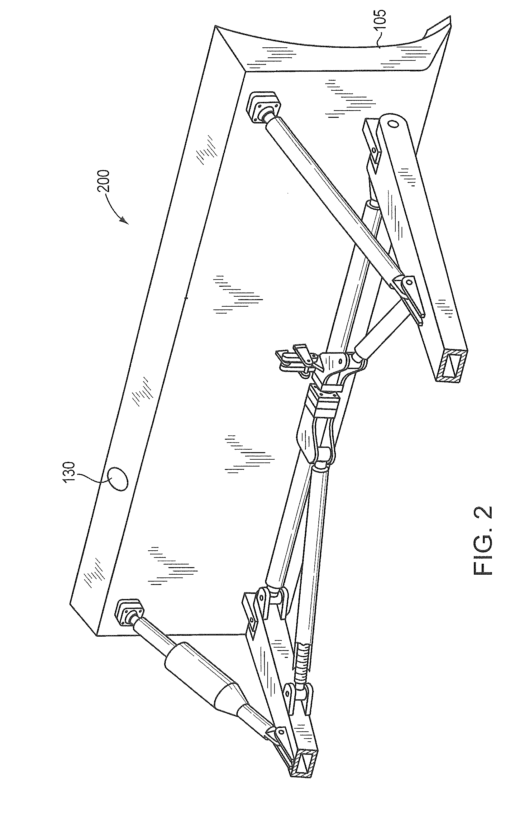
[0021]FIG. 1 is a side view of an exemplary heavy equipment vehicle 100, e.g., a bulldozer, in which the principles of the present invention may be utilized in accordance with an illustrative embodiment of the present invention. The bulldozer 100 illustratively comprises a working edge, e.g., blade 105. Further, the bulldozer 100 includes an image acquisition device 110 mounted thereon that is configured to obtain images of a target 200 that is operatively interconnected / affixed to the blade 105. The image acquisition device 110 includes a fixed field of view 120 that includes the spatial region within which the target 200 may move during operation of the working edge 105. Illustratively, the image acquisition device 110 comprises a time of flight (TOF) camera. A TOF camera illustrative provides both an intensity value and a distance from the camera for each pixel in the TOF camera's field of view. Operatively interconnected with the image acquisitio...


PUM


Abstract

A system and method for automatically controlling working edges on a heavy equipment vehicle is provided. A GNSS / INS system determines a location of the vehicle. A vision system calculates a location of the working edge in a vision system coordinate system by obtaining images of a target connected to the working edge using a camera with a fixed field view that obtains distance information for each pixel in the fixed field of view. The location is then transformed to the navigation system coordinate system. The transformed location information is used by a working edge control system to control the placement of the working edge.

Description

BACKGROUND OF THE INVENTION[0001]1. Field of the Invention[0002]The present invention relates generally to GNSS / INS systems and more particularly to GNSS / INS systems utilized for heavy equipment navigation and working edge positioning.[0003]2. Background Information[0004]Heavy equipment vehicles typically have one or more working edges (e.g., blades) that are utilized to perform specific functions. Examples of heavy equipment includes, e.g., bulldozers, graders, front end loaders, back hoes, etc. As used herein, the term working edge refers generally to any component of heavy equipment that performs a specific function in which precise positioning may be necessary. Examples of working edges may include the blade of a bulldozer or grader, the scoop of a backhoe, etc.[0005]During normal operation, the driver of the heavy equipment will utilize the working edge to perform some function, e.g., using the blade of a bulldozer to level a section of land to a predetermined grade. The work i...

Claims


Application Information

Patent Timeline
Patent Type & Authority Applications(United States)
IPC IPC(8): E02F9/20
CPCE02F9/2025E02F9/2033G05D1/0246E02F3/847G01C21/16
Inventor MORIN, KRISTIAN
Owner HEXAGON TECH CENT GMBH
Why Eureka
Try Eureka