
Confocal optical inspection apparatus and confocal optical inspection method

a technology of optical inspection apparatus and optical inspection method, which is applied in the direction of optical elements, television systems, instruments, etc., can solve problems such as optical system distortion, and achieve the effect of higher level of accuracy

Inactive Publication Date: 2014-06-05
SAMSUNG ELECTRONICS CO LTD
View PDF2 Cites 16 Cited by
  • Summary
  • Abstract
  • Description
  • Claims
  • Application Information

AI Technical Summary

Benefits of technology

The invention is a new and improved confocal optical inspection apparatus and method that can acquire information on an object with higher accuracy despite distortion of the optical system. The apparatus includes a light source, a first opening member, an imaging device, and an information processor. The information processor uses a pre-measured point spread function (PSF) to acquire a corrected confocal image in which distortion of the optical system is removed. The PSF is acquired by imaging the object when it is stationary. The apparatus also includes a second opening member with a plurality of openings that transmit reflected light from the object. The second opening member has larger openings in the insertion and extraction direction than in the direction perpendicular to the scanning direction of the object. The apparatus can inspect objects with high accuracy and efficiency.

Problems solved by technology

However, there is a disadvantage in that distortion may occur in the optical system.

Method used


Image

  • Confocal optical inspection apparatus and confocal optical inspection method
  • Confocal optical inspection apparatus and confocal optical inspection method
  • Confocal optical inspection apparatus and confocal optical inspection method

Examples


Embodiment Construction

[0027]Hereinafter, exemplary embodiments will be described in detail with reference to the attached drawings. The same reference numerals in the drawings denote the same element, and a repeated description will be omitted.

[0028]

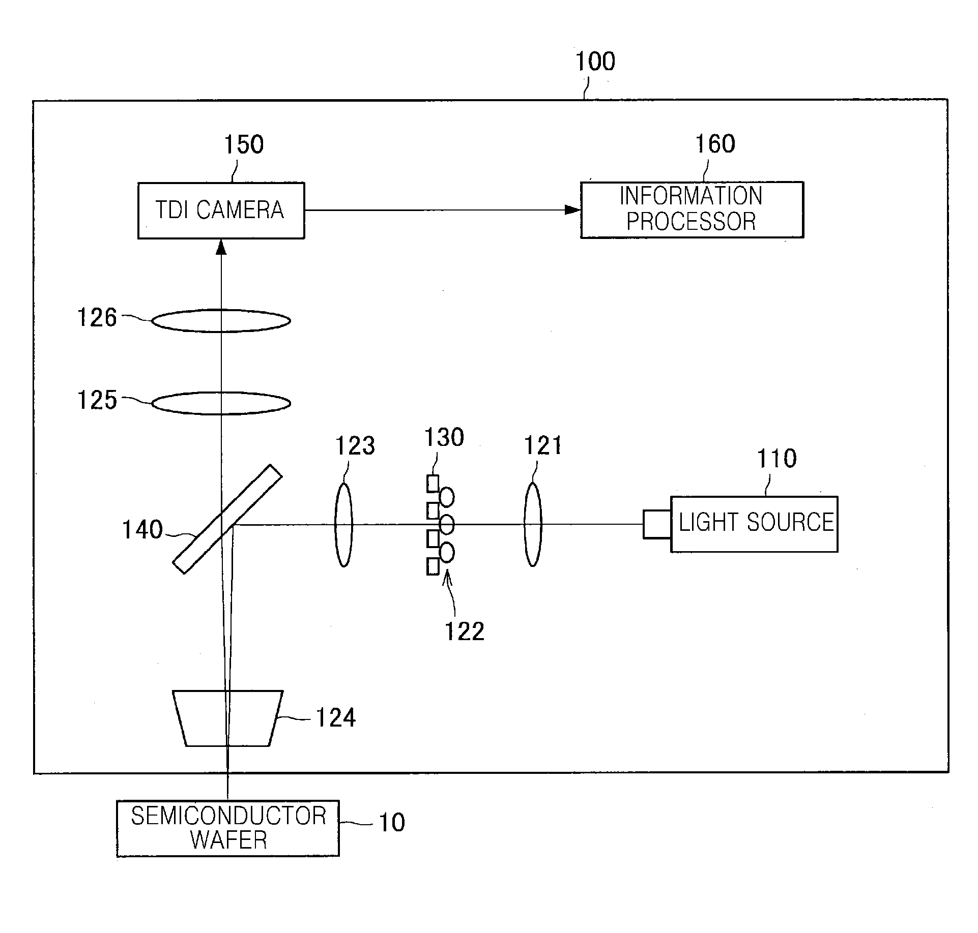
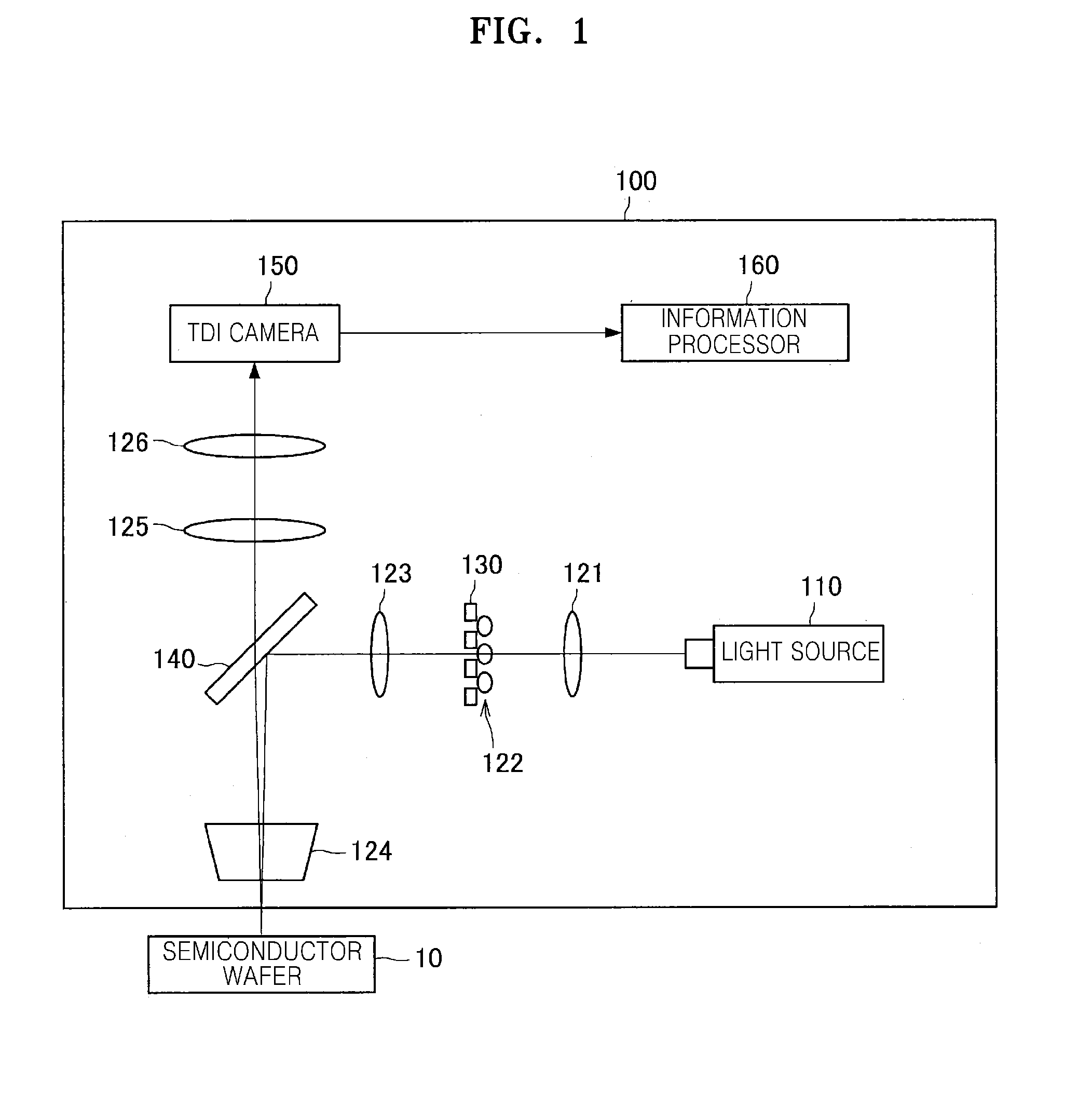
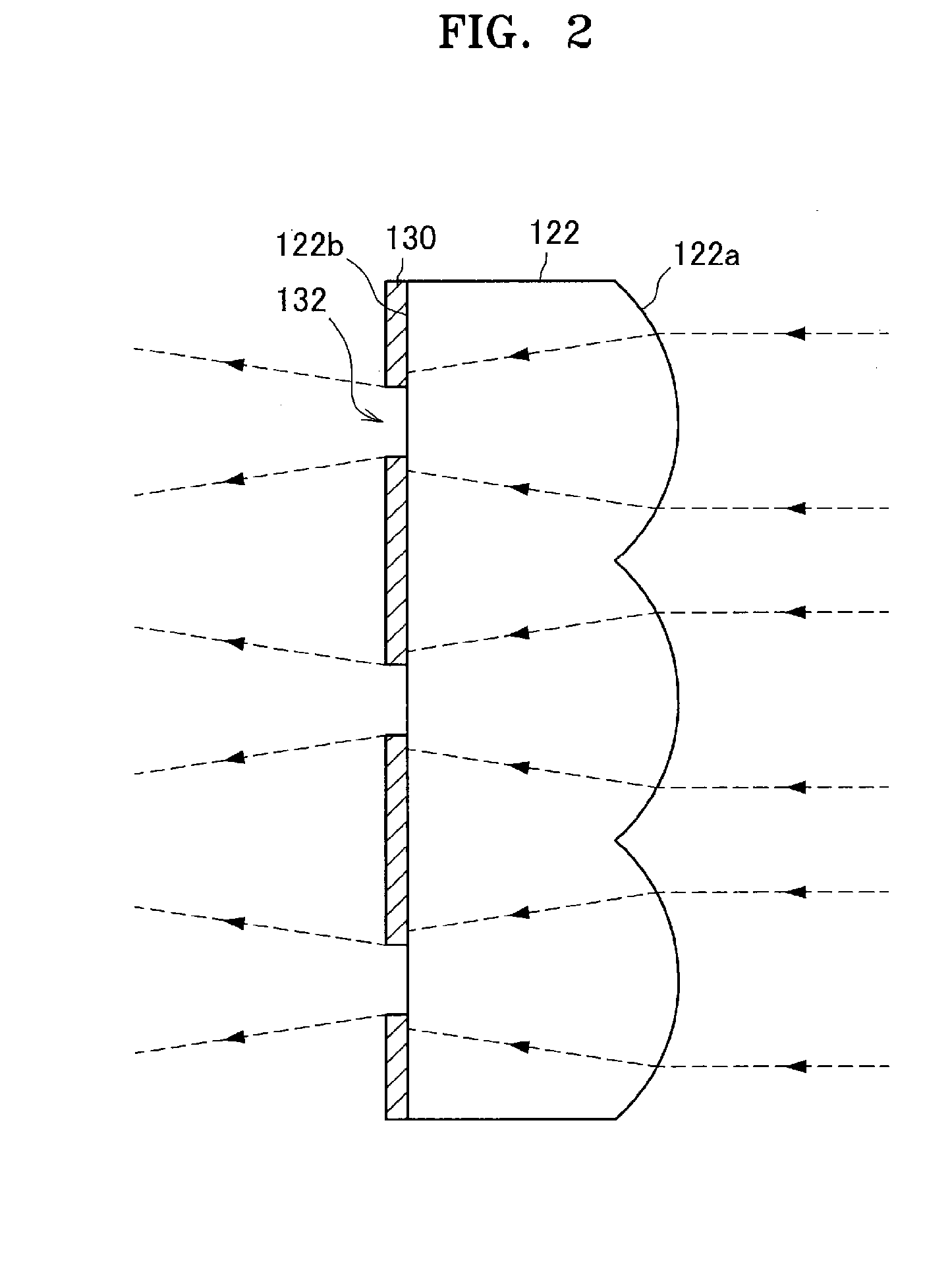
[0029]First, a configuration of a confocal optical inspection apparatus according to an exemplary embodiment will be described with reference to the drawings. FIG. 1 is a schematic diagram illustrating a configuration of a confocal optical inspection apparatus according to an exemplary embodiment. FIG. 2 is a partially enlarged cross-sectional view of a microlens array and a pinhole member of the confocal optical inspection apparatus of FIG. 1, according to an exemplary embodiment. FIG. 3 is a plan view illustrating a configuration example of the pinhole member according to an exemplary embodiment. FIG. 4 is an image showing an example of a spot image in an imaging surface of a time delayed integration (TDI) camera of the confocal optical inspection apparatus...


PUM


Abstract

The confocal optical inspection apparatus that acquires a confocal image of an object and inspects the object includes a light source that emits illumination light; a first opening member that divides the illumination light emitted from the light source into illumination light beams, the first opening member having openings; an imaging device that acquires an image according to the respective illumination light beams reflected by the object; and an information processor that acquires a corrected confocal image in which distortion of an optical transmission path of the confocal optical inspection apparatus is removed from a time delayed integration (TDI) image obtained by a TDI operation of the imaging device, using a pre-measured point spread function (PSF) indicating optical characteristics of the confocal optical inspection apparatus.

Description

CROSS-REFERENCE TO RELATED APPLICATIONS[0001]This application claims priority from Japanese Patent Application No. 2012-265692, filed on Dec. 4, 2012, in the Japanese Patent Office and from Korean Patent Application No. 10-2013-0142337, filed on Nov. 21, 2013, in the Korean Intellectual Property Office, the disclosures of which are incorporated by reference herein in their entireties.BACKGROUND[0002]1. Field[0003]Apparatuses, devices, and articles of manufacture consistent with the present disclosure relate to a confocal optical inspection apparatus that inspects an object using a confocal-type optical system, and a confocal optical inspection method.[0004]2. Description of the Related Art[0005]A confocal microscope may obtain a high resolution image of an object using a confocal optical system.[0006]In a confocal microscope, when an observation region of an object is far larger than one image shown by an object lens, a process such as imaging of a series of images is required. For ...

Claims


Application Information

Patent Timeline
IPC IPC(8): G02B21/00G01N21/88
CPCG02B21/0016G02B21/0028G02B21/008G02B21/365G01N21/9501G01N21/8806
Inventor MITSUHIRO, TOGASHIMITSUNORI, NUMATASHINJI, UEYAMA
Owner SAMSUNG ELECTRONICS CO LTD
Learn More